Temperature Indicator Transmitter
Temperature Indicator Transmitter
In the landscape of industrial process control, the temperature indicator transmitter serves as a critical bridge between physical thermal states and digital control logic. While often viewed as a standalone instrument, its role is deeply integrated with other process variables, particularly in the realm of level measurement. For engineers and facility managers, understanding the nuances of how these devices operate, their selection criteria, and their impact on overall system accuracy is essential for maintaining operational efficiency and safety.
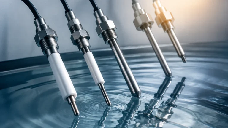
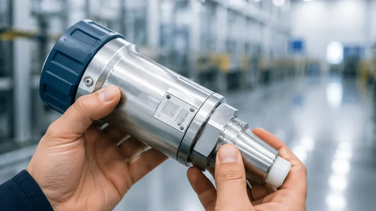
A temperature indicator transmitter is an integrated device that combines a temperature sensor (typically an RTD or thermocouple), a local visual display (the indicator), and an electronic circuit that converts the sensor's signal into a standardized output (the transmitter). This dual functionality allows for both immediate field verification by technicians and remote monitoring by a Distributed Control System (DCS) or Programmable Logic Controller (PLC).
Measurement Principles and Technology
The foundation of any temperature indicator transmitter lies in its sensing element. To select the right instrument, one must first understand the two primary technologies used in industrial environments: Resistance Temperature Detectors (RTDs) and Thermocouples.
Resistance Temperature Detectors (RTDs)
RTDs operate on the principle that the electrical resistance of a metal increases as its temperature rises. The most common type is the Pt100, which has a resistance of 100 ohms at 0°C (32°F). RTDs are favored in B2B applications for their high accuracy, excellent stability over time, and repeatability. They are generally used for temperature ranges between -200°C and +600°C.
Thermocouples
Thermocouples consist of two dissimilar metal wires joined at one end (the sensing junction). When there is a temperature gradient between the sensing junction and the reference junction, a small voltage is produced via the Seebeck effect. Thermocouples are preferred for extremely high-temperature applications (up to 1700°C or more) and are more robust in high-vibration environments, though they generally offer lower accuracy than RTDs.
The Transmitter Circuit
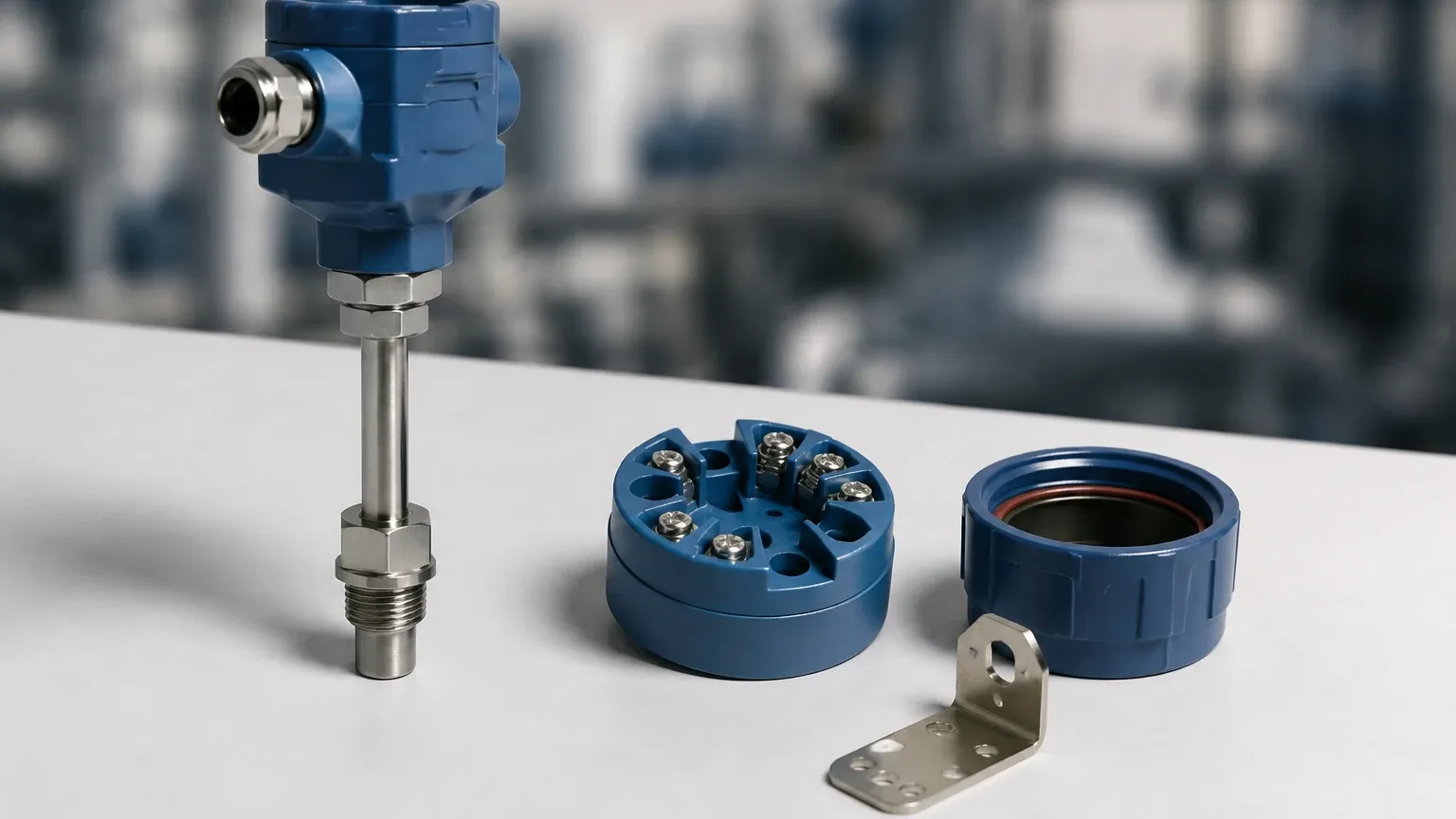
The transmitter component receives the millivolt signal from a thermocouple or the resistance change from an RTD. It then linearizes this signal and converts it into a standard industrial output, most commonly a 4-20mA current loop. This signal is highly resistant to electrical noise and can be transmitted over long distances without significant degradation. Modern units often include HART (Highway Addressable Remote Transducer) protocols, allowing for digital communication over the same analog wires.
The Synergy Between Temperature and Level Measurement
Within the scope of industrial automation, temperature measurement is rarely an isolated requirement. For manufacturers like Welk, temperature data is a fundamental input for accurate level measurement. The Main Page of many industrial instrument providers highlights how these variables interact.
1. Hydrostatic Level Compensation: In hydrostatic level transmitters, the pressure exerted by a liquid column is used to calculate the level. However, liquid density changes with temperature. Without a temperature indicator transmitter providing real-time data, the level calculation may drift as the process fluid heats or cools.
2. Ultrasonic Level Accuracy: Ultrasonic sensors measure the time it takes for a sound wave to bounce off a surface. Since the speed of sound in air or gas varies significantly with temperature, an integrated or external temperature sensor is required to calibrate the distance calculation.
3. Chemical Stability: In chemical storage, maintaining a specific temperature range is vital for preventing crystallization or hazardous reactions. The local indicator allows field operators to confirm safety parameters at the tank side while the transmitter alerts the central control room.
Key Evaluation Criteria for Selection
Selecting a temperature indicator transmitter requires a balance between technical specifications and environmental constraints. Engineers should evaluate the following factors:
Accuracy and Class
For RTDs, accuracy is typically defined by classes (Class AA, A, or B). A Class A Pt100 sensor offers an accuracy of ±(0.15 + 0.002|t|)°C. For critical processes, such as those in pharmaceutical or food grade applications, higher precision classes are mandatory.
Output and Communication
While 4-20mA is the industry standard, consider if your infrastructure supports or requires digital protocols. HART, Modbus RS485, or Foundation Fieldbus can provide additional diagnostic data, such as sensor health and electronics temperature, which aids in predictive maintenance.
Housing and Environmental Ratings
Industrial environments can be harsh. Transmitters should be housed in materials suited for the atmosphere. Aluminum alloy is common for general industrial use, while 316 stainless steel is required for corrosive or marine environments. Look for IP67 or NEMA 4X ratings to ensure protection against dust and water ingress.
Local Display Options
The "indicator" portion of the device can be an LCD or LED display. LCDs are better for high-light environments and consume less power, while LEDs are more visible in dark or low-light indoor facilities. Some indicators also provide bar graphs for a quick visual reference of the process value relative to the full scale.
Practical Selection Table
| Feature | RTD-Based Transmitter | Thermocouple-Based Transmitter |
| :— | :— | :— |
| Temperature Range | -200°C to +600°C | -200°C to +1700°C |
| Typical Accuracy | High (±0.1°C to ±0.5°C) | Moderate (±0.5°C to ±2.0°C) |
| Long-term Stability | Excellent | Fair (subject to drift) |
| Response Time | Slower (due to mass) | Faster |
| Best Use Case | Precision chemical/food processing | High-heat furnaces / Kilns |
| Common Output | 4-20mA / HART | 4-20mA / HART |
Installation Considerations and Best Practices
Proper installation is as important as the instrument's specifications. Failure to follow engineering best practices can lead to measurement errors known as "stem conduction" or mechanical failure.
* Thermowells: In pressurized or corrosive pipelines, never install a temperature indicator transmitter directly into the process. Use a thermowell. This allows the sensor to be removed for calibration or replacement without shutting down the process or draining the tank.
* Insertion Length: To avoid errors caused by ambient temperature bleeding through the sensor housing (stem conduction), the sensor should be inserted into the process at a depth of at least 10 times the diameter of the protection tube.
* Wiring and Shielding: Use twisted-pair shielded cables for the 4-20mA loop to minimize electromagnetic interference (EMI) from nearby motors or power lines. Ensure the shield is grounded at only one end to prevent ground loops.
* Mounting Orientation: While the transmitter can often be mounted in any orientation, ensure the local display is positioned for easy reading by operators and that the conduit entries point downward to prevent moisture from traveling along the cable into the housing.
Common Risks and Limitations
Despite their reliability, temperature indicator transmitters are subject to specific risks that must be managed:
1. Sensor Drift: Over time, the physical properties of RTDs and thermocouples change due to thermal cycling and contamination. Regular calibration against a known standard is required to maintain accuracy.
2. Vibration: Excessive vibration can break the delicate wires inside a sensor or damage the electronics of the transmitter. In high-vibration environments, look for "vibration-resistant" builds or use remote-mounted transmitters where the electronics are separated from the sensor head.
3. Ambient Temperature Limits: The electronic components in the transmitter head have operating limits (typically -40°C to +85°C). If the process is extremely hot, use an extension neck on the thermowell to move the transmitter head away from the heat source.
Frequently Asked Questions (FAQ)
Q: Can I change the temperature range of a transmitter in the field?
A: Yes, most modern digital temperature indicator transmitters are "rangeable." Using a HART communicator or a PC-based configuration tool, you can adjust the 4mA and 20mA points within the sensor's physical limits.
Q: What is the difference between a 2-wire and a 3-wire RTD transmitter?
A: This refers to the connection between the sensor and the transmitter. A 3-wire or 4-wire configuration compensates for the resistance of the lead wires, providing much higher accuracy than a simple 2-wire connection, especially over long distances.
Q: Why is my indicator showing a different value than the DCS?
A: This is often due to a scaling mismatch. Ensure that the 4-20mA range programmed into the transmitter matches the input scaling configured in the DCS. It can also be caused by signal loop resistance exceeding the transmitter's drive capability.
Q: Are these devices safe for use in explosive atmospheres?
A: Many temperature indicator transmitters are available with Intrinsically Safe (IS) or Flameproof (Ex d) certifications. Always check the nameplate for the specific ATEX, IECEx, or UL ratings required for your hazardous zone.
Final Project Confirmation
Before finalizing a purchase or installation plan, project teams should confirm the following details to ensure the temperature indicator transmitter meets the application requirements:
* Process Compatibility: Confirm that the thermowell material is chemically compatible with the process fluid.
* Pressure Ratings: Ensure the thermowell and process connection (flange or thread) can withstand the maximum system pressure, including potential surges.
* Control Loop Power: Verify that the PLC/DCS power supply can provide sufficient voltage (typically 12-36V DC) to power the transmitter and overcome loop resistance.
For comprehensive technical specifications and to explore how temperature integration improves level measurement reliability, engineers are encouraged to Review product options and application support to align their instrument selection with specific industrial automation goals.