How to Design Safe Measurement Circuits for High-energy Power Systems
How to Design Safe Measurement Circuits for High-energy Power Systems
In industrial environments such as water treatment plants, chemical processing facilities, and oil and gas refineries, level measurement instruments often operate in close proximity to high-energy power systems. Designing measurement circuits that can withstand the electrical stresses of these environments is not merely a matter of accuracy; it is a critical safety requirement. High-energy systems, characterized by high voltage and the potential for high fault currents, pose significant risks including arc flashes, transient overvoltages, and equipment failure.
When integrating sensors like radar level meters or ultrasonic transmitters into a facility's automation architecture, engineers must ensure that the measurement loop is isolated and protected from the primary power distribution. This guide explores the principles of safe circuit design, the importance of measurement categories, and practical steps for implementing robust level measurement solutions.
Understanding the Risks of High-Energy Environments
Before detailing the design of measurement circuits, it is essential to understand the specific hazards associated with high-energy power systems. These systems typically involve voltages exceeding 480V AC and can deliver thousands of amperes during a short-circuit event.
Transient Overvoltages
Transients are momentary surges in voltage that can reach several thousand volts. They are often caused by lightning strikes, switching of inductive loads (such as large motors for pumps), or utility grid fluctuations. If a level transmitter is connected to a circuit without adequate transient protection, these surges can bridge the insulation, leading to catastrophic failure and potential injury to personnel.
Arc Flash Hazards
An arc flash occurs when an electric current passes through the air between conductors or from a conductor to the ground. In high-energy systems, the energy released can be immense. Measurement circuits that are improperly fused or lack sufficient clearance can inadvertently trigger an arc flash during maintenance or due to component failure.
Measurement Principles and Safety Categories
The International Electrotechnical Commission (IEC) defines specific measurement categories (CAT) under standard IEC 61010-1. These categories determine the level of transient stress a circuit is designed to withstand. When selecting or designing circuits for industrial level measurement, understanding these categories is the first step toward safety.
| Category | Description | Typical Application |
| :— | :— | :— |
| CAT I | Protected electronic circuits. | Signal level electronics, low-voltage telecommunications. |
| CAT II | Local-level electrical distribution. | Receptacles and household loads. |
| CAT III | Building distribution level. | Three-phase distribution, including large motors and heavy-duty industrial lighting. |
| CAT IV | Source of installation. | Utility connection, outside overhead lines, and underground service entrances. |
For most industrial level measurement applications, instruments are connected to CAT III environments. This means the measurement circuit must be designed to handle transients of up to 6,000V for a 600V system. If you are evaluating sensors for these environments, you can Review product options and application support to ensure the hardware meets the necessary industrial ratings.
Key Design Strategies for Safe Measurement Circuits
Designing a safe circuit requires a multi-layered approach involving isolation, energy limitation, and physical separation.
1. Galvanic Isolation
Galvanic isolation is the most effective way to protect measurement electronics from high-energy power systems. It involves separating the input and output sections of a circuit so that no direct conduction path exists.
* Optical Isolation: Uses light-emitting diodes (LEDs) and phototransistors to transmit signals across an insulation barrier. This is common in digital signal paths and RS485 communications.
* Magnetic Isolation: Uses transformers or giant magnetoresistive (GMR) sensors to couple signals. Transformers are excellent for power isolation, providing high dielectric strength.
* Capacitive Isolation: Uses a changing electric field to transmit data across a dielectric layer. This method is often used for high-speed digital isolators.
2. Creepage and Clearance Distances
In high-voltage design, physical distance is a primary insulator.
* Clearance: The shortest distance through air between two conductive parts. This prevents arcing through the air.
* Creepage: The shortest distance along the surface of an insulating material between two conductive parts. This prevents tracking, where a conductive path forms on the surface of the insulator due to moisture or contamination.
For a 600V industrial system, a minimum clearance of 5.5 mm and a creepage distance of 8 mm are often required, depending on the pollution degree of the environment.
3. Overcurrent and Overvoltage Protection
Every measurement circuit must include components that limit energy during a fault.
* Fuses: High-breaking capacity (HBC) fuses should be used. Unlike standard glass fuses, HBC fuses are filled with sand to extinguish the arc that forms when the fuse blows in a high-energy circuit.
* Metal Oxide Varistors (MOVs): These components clamp overvoltage transients to a safe level by decreasing their resistance as voltage increases.
* Transient Voltage Suppressors (TVS): These diodes react faster than MOVs and are used to protect sensitive semiconductor components in level transmitters.
Selecting Level Measurement Instruments for Safe Integration
When choosing level measurement technology, the power environment dictates the instrument's electrical specifications. Below is a comparison of common level measurement technologies and their typical integration considerations in high-energy systems.
| Technology | Typical Power Supply | Safety Considerations |
| :— | :— | :— |
| Radar Level Meters | 24V DC (Loop-powered) | High immunity to EMI; requires isolated 4-20mA loops. |
| Ultrasonic Sensors | 24V DC or 110/220V AC | Ensure internal isolation between power and transducer circuits. |
| Hydrostatic Transmitters | 12-36V DC | Submerged cables must have high dielectric strength and surge protection at the terminal box. |
| Magnetic Level Gauges | Passive (Mechanical) | Safe for high-energy areas; switches/transmitters must be EX-rated if near volatile power sources. |
The Role of Intrinsic Safety (IS)
In environments where high-energy power systems coexist with explosive atmospheres (common in chemical and oil & gas sectors), measurement circuits should follow Intrinsic Safety (IS) principles. IS circuits limit the total energy (electrical and thermal) available to a level that cannot ignite the surrounding atmosphere. This is achieved through the use of Zener barriers or galvanic isolators installed in a safe area.
Practical Installation and Maintenance Considerations
Even a perfectly designed circuit can become hazardous if installed incorrectly. Follow these engineering guidelines to maintain the integrity of the measurement system:
1. Cable Separation: Never run low-voltage measurement signal cables (e.g., 4-20mA) in the same conduit or tray as high-voltage power cables. Maintain a minimum separation of 300 mm (approximately 12 inches) to prevent electromagnetic interference (EMI) and accidental contact.
2. Proper Grounding: Ensure that the instrument housing is grounded to the plant's equipotential bonding system. This provides a low-impedance path for fault currents and reduces the risk of the instrument chassis becoming energized.
3. Enclosure Selection: Use enclosures with appropriate IP (Ingress Protection) ratings. In high-energy areas, dust and moisture can lead to surface tracking and insulation breakdown. An IP66 or IP67 rating is recommended for most industrial level measurement applications.
4. Shielding: Use shielded twisted-pair cables for all measurement signals. The shield should be grounded at only one end (usually the PLC or control room end) to prevent ground loops.
Limitations and Challenges
While isolation and protection components enhance safety, they introduce certain limitations:
* Signal Degradation: Excessive filtering or isolation stages can introduce latency or phase shifts in high-speed digital communications.
* Space Constraints: Providing adequate creepage and clearance distances often results in larger circuit boards and enclosures, which may be difficult to fit in compact sensor heads.
* Cost: High-breaking capacity fuses and high-grade galvanic isolators increase the initial capital expenditure of the measurement system.
Frequently Asked Questions (FAQs)
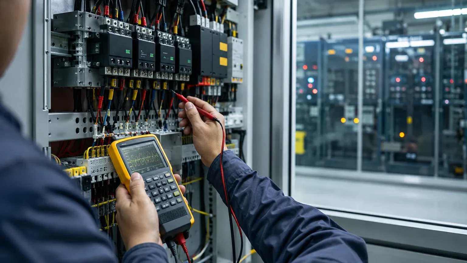
Q: Can I use a standard multimeter to test circuits in a high-energy system?
A: No. You must use a multimeter rated for the appropriate measurement category (e.g., CAT III 600V or CAT IV 600V). Using a lower-rated meter can lead to the device exploding in your hands if a transient occurs during measurement.
Q: Why is 24V DC preferred for level transmitters in industrial plants?
A: 24V DC is considered a Safety Extra-Low Voltage (SELV). It significantly reduces the risk of electric shock for maintenance personnel and simplifies the design of the measurement circuit compared to line-powered (110/220V AC) instruments.
Q: How often should surge protection components be replaced?
A: MOVs and other surge suppressors degrade each time they absorb a spike. They should be inspected annually and replaced if there are signs of discoloration or if the system has experienced a major electrical event like a nearby lightning strike.
Conclusion
Designing safe measurement circuits for high-energy power systems requires a disciplined approach to electrical engineering. By adhering to IEC measurement categories, implementing robust galvanic isolation, and ensuring proper physical separation of cables, engineers can protect both their equipment and their personnel. When selecting level measurement hardware, always verify that the instrument's electrical ratings align with the specific demands of your facility's power infrastructure. For more detailed technical specifications on industrial-grade measurement tools, visit the Main Page of our product catalog.
Download How to Design Safe Measurement Circuits for High-energy Power Systems as a PDF