Ultrasonic Water Flowmeter
Ultrasonic Water Flowmeter
In the realm of industrial automation and resource management, the accurate measurement of liquid movement is critical for process efficiency, cost control, and regulatory compliance. The ultrasonic water flowmeter has emerged as a preferred technology for many B2B applications due to its non-invasive nature, lack of moving parts, and high reliability. As a professional manufacturer of industrial measurement instruments, Welk provides advanced solutions that integrate seamlessly into complex water treatment, chemical, and industrial systems. This guide explores the engineering principles, selection criteria, and installation best practices for ultrasonic flow measurement.
Measurement Principles of Ultrasonic Flowmeters
To select the correct instrument, engineers must first understand the two primary physical principles used in ultrasonic flow measurement: Transit-Time and Doppler Effect.
Transit-Time Method
This is the most common principle used for clean water applications. The system employs two transducers that function as both ultrasonic transmitters and receivers. They are mounted on either side of the pipe, either across from each other or on the same side using a reflective path.
The transducers transmit pulses of high-frequency sound through the moving liquid. A pulse traveling with the flow (downstream) moves faster than a pulse traveling against the flow (upstream). The flowmeter measures the extremely small time difference (nanoseconds) between these two signals. This time difference is directly proportional to the velocity of the water. Since the cross-sectional area of the pipe is known, the device calculates the volumetric flow rate.
Doppler Effect Method
While transit-time meters require relatively clean fluid to allow the signal to pass through, Doppler flowmeters rely on reflections. This method uses the frequency shift of an ultrasonic signal reflected off suspended solids or entrained air bubbles (discontinuities) in the moving liquid. If the water is perfectly clean, a Doppler meter will not function. Therefore, Doppler technology is typically reserved for wastewater, slurries, or aerated liquids where transit-time signals would be attenuated or blocked.
Types of Ultrasonic Water Flowmeters
Ultrasonic flowmeters are categorized by their mechanical design and how they interface with the piping system. Choosing between these types depends on whether the installation is a new build or a retrofit of an existing line.
1. Clamp-on Ultrasonic Flowmeters
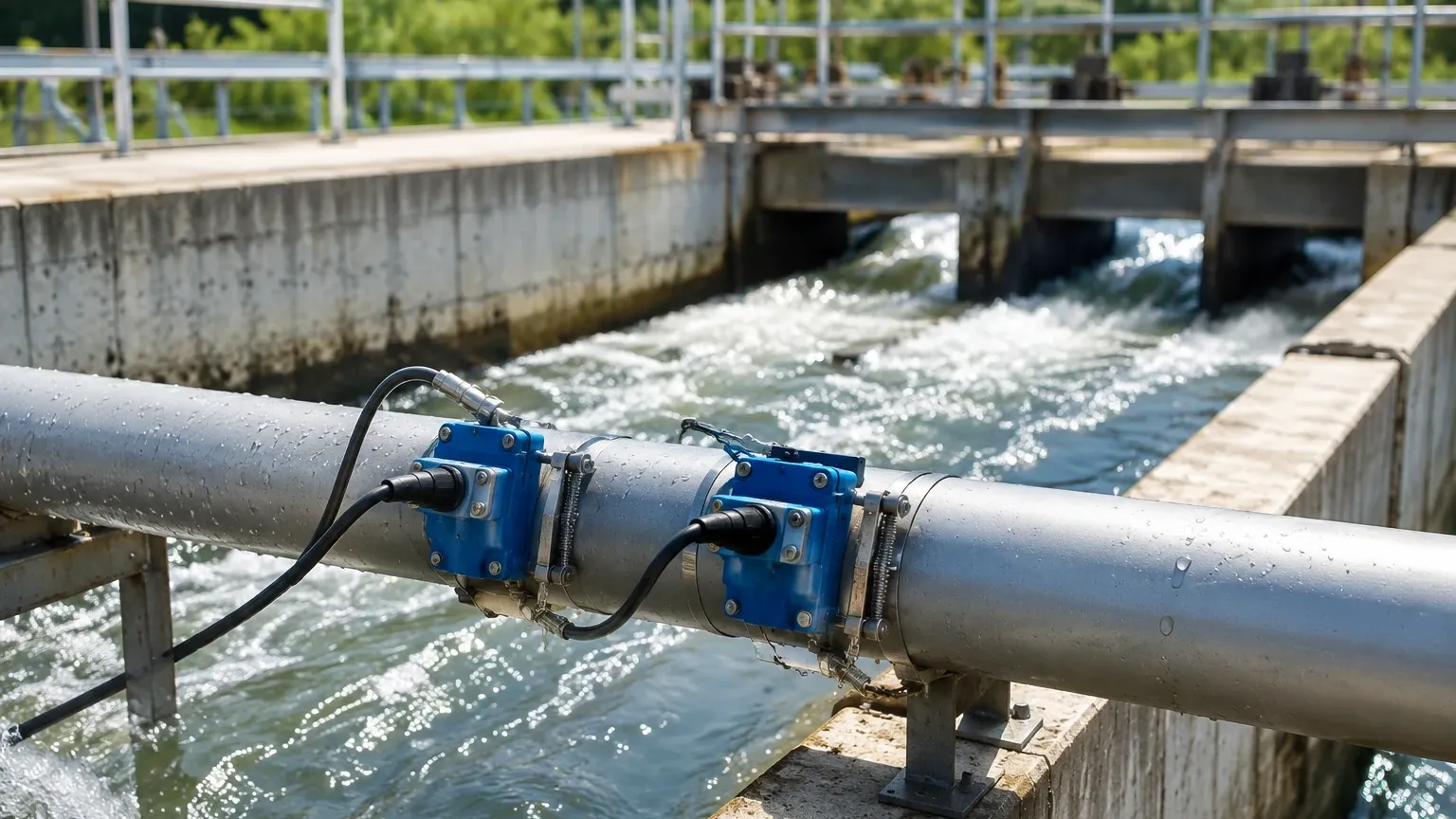
These are external devices where the transducers are strapped to the outside of the pipe. They are highly valued in the chemical and oil and gas industries because they do not require cutting into the pipe or shutting down the process.
* Advantages: Zero pressure drop, no risk of leakage, and no contact with corrosive or high-pressure fluids.
* Applications: Retrofitting existing plants, measuring corrosive chemicals, and temporary flow surveys.
2. Inline (Spool Piece) Flowmeters
In this configuration, the transducers are integrated into a factory-calibrated pipe section (spool). The entire section is bolted into the pipeline via flanges.
* Advantages: Higher accuracy (often better than ±0.5%) and less sensitive to pipe wall conditions or internal scaling.
* Applications: High-precision billing, water distribution networks, and critical process control.
3. Portable/Handheld Flowmeters
These are battery-powered clamp-on units used by technicians for spot-checking or verifying the accuracy of existing meters. They are essential tools for facility maintenance and energy audits.
Selection Criteria and Technical Specifications
When evaluating an ultrasonic water flowmeter for a specific project, several technical parameters must be confirmed. The following table provides a comparison to assist in the selection process:
| Feature | Clamp-on (Transit-Time) | Inline (Transit-Time) | Doppler (Clamp-on) |
| :— | :— | :— | :— |
| Best Fluid Type | Clean water, deionized water | Clean to slightly dirty water | Wastewater, slurries, aerated liquids |
| Accuracy | ±1.0% to ±3.0% of rate | ±0.5% to ±1.0% of rate | ±2.0% to ±5.0% of FS |
| Pipe Sizes | 15 mm to 6000 mm | 15 mm to 1200 mm | 25 mm to 6000 mm |
| Installation Cost | Low (No pipe cutting) | High (Requires shutdown/cutting) | Low (No pipe cutting) |
| Maintenance | Low (External sensors) | Moderate (Internal sensors) | Low (External sensors) |
| Pressure Drop | Zero | Negligible | Zero |
For engineers managing complex liquid systems, it is often necessary to pair flow data with level data. Reviewing product options and application support on the Main Page can help in selecting a comprehensive suite of sensors, including radar and ultrasonic level meters, to ensure total tank and pipeline visibility.
Installation Considerations
The performance of an ultrasonic water flowmeter is heavily dependent on the quality of the installation. Unlike mechanical meters, ultrasonic waves are sensitive to turbulence and pipe wall integrity.
1. Straight Pipe Requirements
To ensure a stable flow profile, the meter must be installed in a section of straight pipe. The standard engineering rule is "10D Upstream and 5D Downstream." This means there should be a straight run of pipe equal to 10 times the pipe diameter before the meter and 5 times the diameter after the meter. Obstructions like valves, elbows, or pumps create turbulence that can cause significant measurement errors.
2. Transducer Mounting Modes
For clamp-on meters, the mounting configuration depends on the pipe diameter and fluid properties:
* V-Method: The signal bounces off the opposite wall once. This is the standard for pipes ranging from 25 mm to 400 mm (approx. 1" to 16").
* Z-Method: Transducers are placed on opposite sides of the pipe. The signal passes through the fluid only once. This is used for large pipes (above 400 mm) or where the fluid is slightly attenuating.
* W-Method: The signal bounces three times. This is used for very small pipes (below 50 mm) to increase the time-of-flight and improve resolution.
3. Coupling Agents and Pipe Surface
For external sensors, the gap between the transducer and the pipe wall must be filled with a coupling agent (typically a silicone grease or gel) to eliminate air pockets. The pipe surface must be cleaned of rust, loose paint, or scale. In some cases, the pipe must be sanded down to bare metal to ensure acoustic conductivity.
Limitations and Common Risks
While ultrasonic technology is versatile, it is not a "one-size-fits-all" solution. Engineers should be aware of the following limitations:
* Full Pipe Requirement: The pipe must be 100% full of liquid. If there is air at the top of the pipe, the ultrasonic signal will be lost, and the meter will report an error or zero flow.
* Lined Pipes: Some pipe linings (like loose plastic liners or mortar) can have an air gap between the liner and the host pipe. This air gap acts as an acoustic barrier, preventing the signal from reaching the water.
* Signal Attenuation: Extremely thick slurries or liquids with high concentrations of bubbles can absorb the ultrasonic energy, making transit-time measurement impossible.
* Scaling and Fouling: Internal scaling on the pipe wall can change the internal diameter (ID) used for flow calculations, leading to systematic errors in volumetric reporting.
Frequently Asked Questions (FAQs)
Q: Can an ultrasonic water flowmeter measure flow in both directions?
A: Yes, most modern transit-time ultrasonic meters are inherently bidirectional. They can measure and totalize flow in both the forward and reverse directions, which is useful for applications like reservoir management or cooling loops.
Q: How does temperature affect accuracy?
A: The speed of sound in water changes with temperature (e.g., ~1450 m/s at 10°C vs. ~1540 m/s at 50°C). High-quality meters include temperature compensation algorithms or allow for an external RTD input to adjust the calculation in real-time.
Q: Is it possible to use a clamp-on meter on old cast iron pipes?
A: It is possible, but challenging. Old cast iron often has internal pitting or heavy scaling that scatters the ultrasonic signal. In these cases, the Z-method is usually required, and significant surface preparation is mandatory.
Q: What is the typical lifespan of an ultrasonic sensor?
A: Since there are no moving parts to wear out, the electronics can last 10-15 years. For clamp-on models, the coupling gel may need to be replenished every few years if it dries out, especially in high-temperature environments.
Conclusion
The ultrasonic water flowmeter represents a sophisticated balance of physics and digital signal processing, offering a reliable way to monitor water usage without compromising pipe integrity. By understanding the distinction between transit-time and Doppler methods and adhering to strict installation guidelines regarding pipe runs and surface preparation, industrial operators can achieve high-precision measurements.
For professionals seeking to optimize their fluid management systems, integrating flow data with reliable level measurement is the next logical step. Welk offers a range of industrial instruments designed for the rigors of the chemical, water treatment, and automation sectors. To explore how these technologies can be customized for your specific application, visit the Main Page for detailed technical specifications and expert support.