Electromagnetic Insertion Flow Meter
Electromagnetic Insertion Flow Meter
In industrial process control, measuring the flow of conductive liquids in large-diameter pipelines presents significant logistical and financial challenges. While full-bore electromagnetic flow meters offer high accuracy, their cost and weight increase exponentially with pipe size. The electromagnetic insertion flow meter serves as a versatile and cost-effective alternative for these applications. By measuring the local flow velocity at a specific point within the pipe cross-section, these instruments provide reliable volumetric flow data for water treatment, HVAC, and chemical processing industries.
This guide examines the technical principles, selection criteria, and installation requirements for electromagnetic insertion flow meters, providing engineers with the factual basis needed to integrate these sensors into existing or new piping networks.
Understanding the Measurement Principle
The electromagnetic insertion flow meter operates based on Faraday’s Law of Electromagnetic Induction. This principle states that a conductor (in this case, a conductive liquid) moving through a magnetic field generates an electrical voltage. The relationship is expressed by the formula:
E = kBDv
Where:
* E is the induced voltage.
* k is a constant coefficient.
* B is the magnetic field strength.
* D is the distance between the electrodes.
* v is the velocity of the fluid.
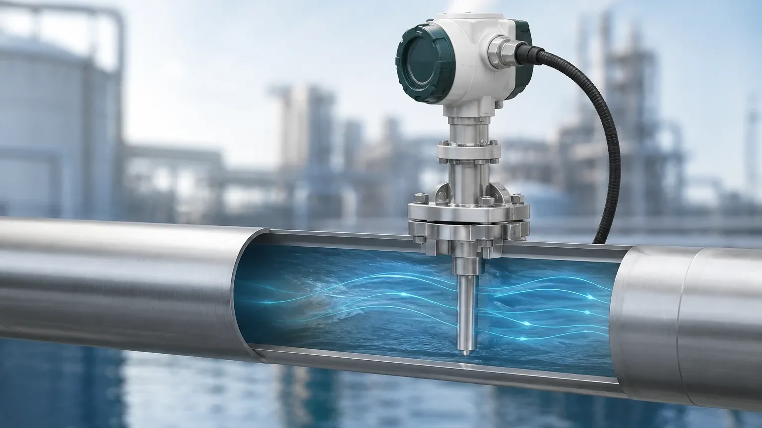
In an insertion-style meter, the sensor probe is inserted through a nozzle on the pipe wall. The probe head contains an electromagnetic coil that generates a magnetic field and a pair of electrodes that contact the fluid. As the fluid flows past the probe, the electrodes detect the induced voltage, which is directly proportional to the local flow velocity.
Unlike full-bore meters that measure the average velocity across the entire pipe area, an insertion meter measures a "point velocity." To calculate the total volumetric flow rate ($Q = A \times v_{avg}$), the transmitter uses a profile correction factor (k-factor) to relate the measured point velocity to the mean velocity of the entire pipe cross-section. This factor accounts for the Reynolds number and the pipe's internal roughness.
Key Components and Construction
A standard electromagnetic insertion flow meter system consists of two primary elements: the sensor probe and the transmitter.
The Sensor Probe
The probe is the wetted part of the instrument. It typically features a stainless steel (316L) body with a specialized sensor head. The electrodes are often made from materials such as 316L stainless steel, Hastelloy C, or Titanium, depending on the chemical aggressiveness of the fluid. The insulation (liner) surrounding the electrodes is usually made of PEEK or PTFE to ensure high chemical resistance and electrical isolation.
The Transmitter
The transmitter provides the excitation current to the probe's coils and processes the low-voltage signal from the electrodes. Modern transmitters offer digital displays, 4-20mA analog outputs, pulse outputs for totalization, and digital communication protocols like Modbus RS485 or HART. For remote monitoring, manufacturers like Welk provide integrated solutions that can be reviewed on their Main Page, where various instrumentation options are detailed.
Selection Criteria for Industrial Applications
Choosing the correct electromagnetic insertion flow meter requires a detailed understanding of the process environment. Because these meters rely on electromagnetic induction, the fluid must be electrically conductive.
1. Fluid Conductivity
The minimum conductivity required for most insertion magmeters is 5 μS/cm (microsiemens per centimeter). This makes them suitable for raw water, wastewater, cooling water, and most acids or alkalis, but unsuitable for hydrocarbons, deionized water, or oil-based fluids.
2. Pipe Size and Material
Insertion meters are generally recommended for pipe diameters ranging from DN150 (6 inches) to DN3000 (120 inches). For pipes smaller than DN150, full-bore meters are usually more practical and accurate. The pipe material must be known to select the appropriate mounting hardware (e.g., carbon steel, stainless steel, or plastic).
3. Pressure and Temperature Ratings
Standard probes are typically rated for pressures up to 1.6 MPa (16 bar), though high-pressure versions are available for specific industrial needs. Temperature limits are defined by the electrode insulation, often ranging from -20°C to +100°C for PEEK or up to +150°C for specialized PTFE constructions.
4. Velocity Range
Most electromagnetic insertion flow meters are designed to measure velocities between 0.1 m/s and 10 m/s. Accuracy is highest in the middle of this range (0.5 m/s to 5 m/s). At very low velocities, the signal-to-noise ratio decreases, which can impact measurement stability.
Comparison: Insertion vs. Full-Bore Electromagnetic Flow Meters
| Feature | Insertion Flow Meter | Full-Bore Flow Meter |
| :— | :— | :— |
| Cost (Large Pipes) | Low (remains stable as pipe size increases) | High (increases exponentially with size) |
| Installation | Simple (single hole, hot-tapping possible) | Complex (requires cutting pipe and flanges) |
| Accuracy | ±1.5% to ±2.0% of reading | ±0.2% to ±0.5% of reading |
| Pressure Drop | Negligible | Zero |
| Maintenance | Can be removed without stopping flow | Requires process shutdown to remove |
| Weight | Lightweight (approx. 5-10 kg) | Very heavy (can exceed 500 kg for large DN) |
Installation Requirements and Best Practices
The accuracy of an electromagnetic insertion flow meter is heavily dependent on the flow profile. If the flow is turbulent or swirling, the point velocity measured by the probe will not accurately represent the average velocity.
Straight Pipe Run Requirements
To ensure a fully developed flow profile, the sensor must be installed in a straight section of pipe. Standard guidelines require:
* Upstream: 10 diameters (10D) of straight pipe after any elbows, valves, or pumps.
* Downstream: 5 diameters (5D) of straight pipe before any subsequent fittings.
If these distances cannot be met, the measurement uncertainty will increase. In some cases, flow straighteners can be used to mitigate the effects of turbulence.
Insertion Depth
The probe must be inserted to a specific depth to capture the representative velocity. There are two common methods:
1. Centerline Method: The sensor head is placed at the exact center of the pipe ($0.5 \times$ Diameter). This is common for smaller pipes or where the flow profile is highly predictable.
2. 1/8th Diameter Method: The sensor is inserted to a depth of $0.125 \times$ Diameter. This is often used in larger pipes to capture the mean velocity point in a turbulent flow profile.
Mounting Orientation
For horizontal pipes, the probe should be installed at the 3 o'clock or 9 o'clock position (the sides of the pipe). This prevents air bubbles (which collect at the top) or sediment (which collects at the bottom) from interfering with the electrode contact. For vertical pipes, the flow should always be upward to ensure the pipe remains completely full of liquid.
Hot Tapping
One of the primary advantages of the electromagnetic insertion flow meter is the ability to perform a "hot tap" installation. Using a ball valve and a specialized insertion tool, the probe can be installed while the pipeline is under pressure, eliminating the need for costly system shutdowns.
Limitations and Operational Constraints
While highly versatile, insertion meters have specific limitations that must be addressed during the engineering phase:
* Profile Sensitivity: Because they only measure at one point, they are more sensitive to upstream disturbances than full-bore meters.
* Full Pipe Requirement: The meter cannot function in partially filled pipes. The electrodes must be completely submerged in the conductive fluid.
* Coating and Fouling: If the fluid contains fats, oils, or greases that coat the electrodes, the signal will be lost. Regular cleaning or the use of self-cleaning electrode designs may be necessary in wastewater applications.
* Conductivity Limits: As mentioned, non-conductive fluids like hydrocarbons or pure chemicals cannot be measured using this technology.
Maintenance and Calibration
Electromagnetic insertion flow meters have no moving parts, which inherently reduces the need for mechanical maintenance. However, periodic verification is recommended:
1. Electrode Cleaning: In applications with high solids or biological growth, the probe should be withdrawn (using the hot-tap valve) and cleaned with a soft cloth or appropriate solvent.
2. Zero-Point Check: This should be performed during commissioning. With the pipe full and the flow at a complete standstill, the transmitter should read zero. If not, a zero-calibration adjustment is required.
3. Insulation Resistance: Periodically checking the resistance between the electrodes and the probe body can identify potential liner failures or moisture ingress.
Frequently Asked Questions (FAQ)
Q: Can an insertion flow meter measure the flow of deionized water?
A: No. Deionized water has extremely low conductivity (usually <1 μS/cm), which is insufficient for the electromagnetic induction principle to work. An ultrasonic or vortex flow meter would be a better choice for this application.
Q: What is the maximum pressure an insertion meter can handle?
A: Standard models typically handle up to 1.6 MPa. However, custom-engineered probes can be designed for higher pressures, provided the mounting nozzle and valve assembly are rated accordingly.
Q: How does pipe roughness affect the measurement?
A: Pipe roughness affects the shape of the velocity profile. Older, corroded pipes have more friction at the walls, leading to a more "peaked" velocity profile. The transmitter's k-factor must be adjusted to account for the internal condition of the pipe for maximum accuracy.
Q: Is it possible to use an insertion meter for steam or gas?
A: No. Electromagnetic flow meters only work with conductive liquids. For steam or gas, differential pressure (orifice plates), vortex, or thermal mass flow meters are required.
Conclusion
The electromagnetic insertion flow meter is a critical tool for industrial flow management, particularly where large pipe diameters make full-bore meters impractical. By adhering to strict installation guidelines—specifically regarding straight pipe runs and insertion depth—engineers can achieve reliable and repeatable measurements. While they offer slightly lower accuracy than their full-bore counterparts, the benefits of lower cost, ease of maintenance, and the ability to install without process interruption make them the preferred choice for many municipal and industrial water applications.
For more information on selecting the right instrumentation for your specific process requirements, including level and flow solutions, you can consult the technical resources available on the Welk Main Page.