Safety Instrumented System Integration
Safety Instrumented System Integration
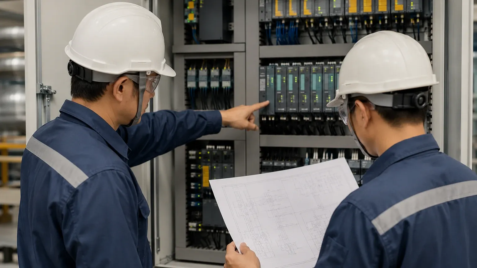
In industrial process environments, the distinction between control and safety is fundamental to operational integrity. While Basic Process Control Systems (BPCS) manage the day-to-day fluctuations of a plant to maintain efficiency and product quality, a Safety Instrumented System (SIS) serves as a dedicated protection layer. Safety instrumented system integration involves the seamless incorporation of sensors, logic solvers, and final elements designed to take a process to a safe state when predetermined conditions are violated. For level measurement, this integration is critical in preventing overfills, dry runs, and catastrophic vessel failures in industries ranging from chemical processing to oil and gas.
Understanding the Fundamentals of SIS and SIL
Before exploring the specifics of level measurement integration, it is essential to define the regulatory and technical framework. The international standards IEC 61508 and IEC 61511 govern the functional safety of electrical, electronic, and programmable electronic safety-related systems.
A Safety Instrumented System is comprised of one or more Safety Instrumented Functions (SIF). Each SIF is designed to achieve a specific Safety Integrity Level (SIL), which is a measure of the required reliability of the safety function. SIL ratings range from 1 to 4, with SIL 3 being the highest level typically encountered in the process industries. Level sensors act as the "eyes" of the SIS, providing the initial data that triggers a safety response.
Measurement Principles for Safety-Critical Level Applications
Effective safety instrumented system integration begins with selecting the correct measurement principle. Each technology has inherent strengths and limitations that impact its suitability for a safety loop.
Radar Level Measurement
Radar level meters, particularly Frequency Modulated Continuous Wave (FMCW) and Guided Wave Radar (GWR), are often preferred for SIS applications. They operate on the Time-of-Flight (ToF) principle, measuring the time it takes for a microwave signal to travel to the product surface and back.
* Advantages for SIS: Non-contact radar is unaffected by changes in density, pressure, or temperature. It offers high diagnostic coverage, as the electronics can often detect a loss of echo or internal hardware failure.
* Limitations: High-foam environments can absorb microwave signals, potentially leading to a signal loss if not correctly specified.
Ultrasonic Level Sensors
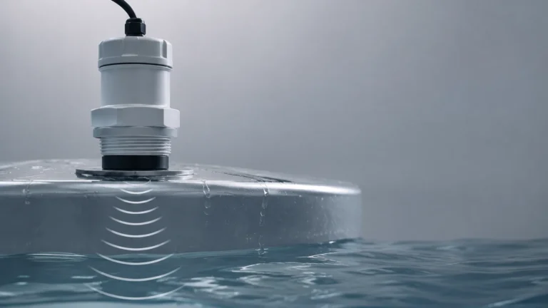
Ultrasonic sensors also use the ToF principle but utilize sound waves instead of electromagnetic waves. They are commonly integrated into safety systems for water treatment and open-tank chemical storage.
* Advantages for SIS: Cost-effective and easy to install. They provide a reliable non-contact solution for stable liquid surfaces.
* Limitations: Sound velocity is temperature-dependent. Furthermore, heavy vapors, dust, or surface turbulence can attenuate the signal, making them less suitable for volatile hydrocarbon service in high-SIL loops.
Hydrostatic Level Transmitters
These sensors measure the pressure exerted by a liquid column. The level is calculated using the formula: *Level = Pressure / (Density × Gravity)*.
* Advantages for SIS: Highly reliable for vented tanks where liquid density remains constant. They are simple to integrate into existing piping via nozzles or flanges.
* Limitations: If the medium's density changes significantly due to temperature shifts or composition changes, the level reading will drift, potentially compromising the safety function.
Magnetic Level Gauges and Switches
Magnetic level gauges provide both a local visual indication and a remote signal via a transmitter or switches mounted on the bypass chamber.
* Advantages for SIS: They offer physical redundancy. A magnetic switch can act as a high-high level alarm independent of the continuous transmitter, providing a secondary layer of protection.
* Limitations: They require a bypass chamber, which introduces additional potential leak points and requires careful mechanical installation.
Key Evaluation Criteria for Safety Instrumented System Integration
Integrating level instruments into an SIS requires more than just selecting an accurate sensor. Engineers must evaluate several technical parameters to ensure the device meets the required SIL.
1. Safe Failure Fraction (SFF): This is the ratio of the average rate of safe failures and dangerous detected failures to the total average failure rate. For a device to be used in a SIL 2 or SIL 3 loop, it must demonstrate a high SFF, typically through rigorous third-party certification.
2. Diagnostic Coverage: Modern industrial instruments from manufacturers like Welk include internal self-monitoring. These diagnostics can detect issues such as crystal buildup on a probe, electronic drift, or power supply fluctuations. Higher diagnostic coverage reduces the probability of a "dangerous undetected" failure.
3. Proof Test Interval: No safety system is "set and forget." Safety instrumented system integration must account for proof testing—manual tests performed to reveal undetected failures. Instruments with longer proof test intervals reduce operational downtime and maintenance costs.
4. Redundancy and Voting Logic: In high-risk applications, a single sensor may not suffice. Integration often involves redundant architectures, such as 1oo2 (one out of two) or 2oo3 (two out of three) voting. This ensures that even if one sensor fails, the safety function can still be performed or a false trip can be avoided.
Selection Table for SIS Level Instruments
| Technology | Typical SIL Capability | Best Use Case | Main Limitation |
| :— | :— | :— | :— |
| Guided Wave Radar | SIL 2 / SIL 3 | High-pressure vessels, low dielectric liquids | Physical contact with medium |
| Non-Contact Radar | SIL 2 / SIL 3 | Corrosive chemicals, large storage tanks | Signal attenuation by heavy foam |
| Ultrasonic | SIL 1 / SIL 2 | Water treatment, sumps | Sensitive to vapor and temperature |
| Hydrostatic | SIL 1 / SIL 2 | Vented tanks, constant density liquids | Density-dependent accuracy |
| Magnetic Switch | SIL 2 | Overfill prevention (Point Level) | Moving parts (float) can stick |
Installation Considerations and Constraints
The physical installation of a level sensor is often where safety instrumented system integration fails or succeeds. Even the most advanced SIL-rated transmitter will provide false data if installed incorrectly.
* Nozzle Positioning: For radar and ultrasonic sensors, the nozzle must be positioned away from the tank wall to avoid false reflections (parasitic echoes). It should also be clear of internal obstructions like agitators or spray balls.
* Stilling Wells and Bypass Chambers: In turbulent tanks, using a stilling well or a bypass chamber can stabilize the liquid surface, providing a cleaner signal for the safety system. However, these must be designed to prevent clogging or buildup.
* Environmental Factors: Ambient temperature extremes can affect electronics. In cold climates, heat tracing may be required for the instrument manifold to prevent the process medium from freezing or becoming too viscous to measure accurately.
* Separation of BPCS and SIS: A core principle of safety engineering is the independence of the safety system. Whenever possible, the SIS level sensor should be a separate physical device from the sensor used for basic process control. This prevents a single point of failure from disabling both the control and the safety functions.
Common Risks and Mitigation in SIS Integration
One of the primary risks in safety instrumented system integration is Common Cause Failure (CCF). This occurs when multiple redundant sensors fail simultaneously due to the same external factor. For example, if three identical ultrasonic sensors are used in a tank where a sudden chemical reaction creates dense foam, all three sensors may lose their signal at the same time.
To mitigate CCF, engineers often employ diverse redundancy. Instead of using three identical radar units, a system might integrate one non-contact radar and one hydrostatic pressure transmitter. Because these technologies rely on different physical principles, they are unlikely to fail for the same reason.
Another risk is nuisance tripping. If a safety system is too sensitive, it may shut down the process frequently without a real hazard, leading to significant economic loss. Proper integration involves fine-tuning the response times and damping factors of the level instruments to balance safety with operational availability.
Frequently Asked Questions (FAQ)
Q: Can any level transmitter be used in a Safety Instrumented System?
A: No. Only instruments that have been designed and certified according to IEC 61508, or those that have a proven-in-use history documented by the end-user, should be integrated into an SIS. Certified devices come with a safety manual specifying their SFF and PFD (Probability of Failure on Demand).
Q: What is the difference between a safety-rated transmitter and a standard one?
A: Safety-rated transmitters undergo more rigorous testing and include hardware and software features specifically designed to detect internal failures. They also provide the necessary documentation for SIL calculations.
Q: How often must SIS level sensors be calibrated?
A: Calibration frequency depends on the specific SIF requirements and the manufacturer's recommendations. However, in an SIS context, the focus is often on the "proof test," which verifies that the instrument can still perform its safety function, rather than just checking its accuracy.
Conclusion
Successful safety instrumented system integration requires a deep understanding of both the process environment and the measurement technologies available. By selecting instruments with high diagnostic coverage and adhering to the principles of independence and redundancy, operators can significantly reduce the risk of industrial accidents. For those looking to implement or upgrade their safety loops, it is advisable to Review product options and application support to ensure the selected hardware aligns with the required Safety Integrity Levels and process conditions. As a professional manufacturer, Welk provides the necessary technical data and reliable instrumentation to support robust safety architectures across global industries.