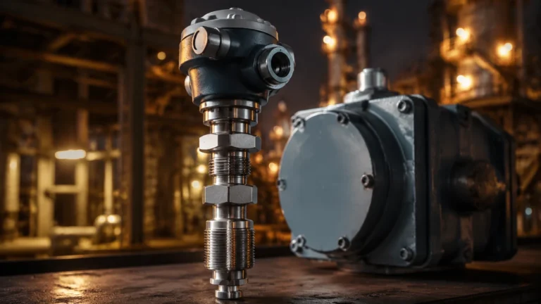
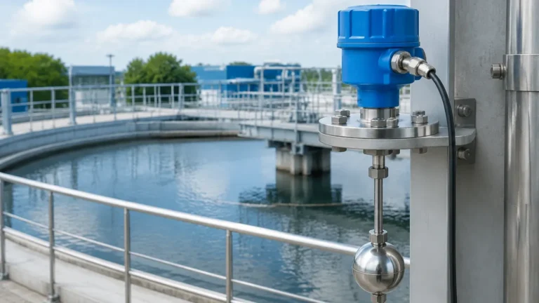
Endres
Endres
In the landscape of industrial process automation, the name Endres—often associated with the global instrumentation leader Endress+Hauser—represents a standard of precision and reliability. For engineers and procurement professionals, navigating the complexities of level measurement requires a deep understanding of the underlying physics, the specific constraints of the application environment, and the technical specifications of the instruments involved. This guide provides a factual overview of industrial level measurement technologies, focusing on the principles, selection criteria, and installation requirements essential for maintaining operational efficiency.
Industrial level measurement is not a one-size-fits-all discipline. Whether managing volatile chemicals in a refinery or monitoring water levels in a municipal treatment plant, the choice of technology impacts both safety and profitability. By examining the core methodologies used by industry leaders, including those found on the Main Page of specialized manufacturers like Welk, operators can better evaluate which solution fits their specific process needs.
Core Measurement Principles and Methodologies
Before selecting an instrument, it is critical to understand the physics of how level is detected. Most industrial applications utilize one of four primary methods: Radar (Time of Flight), Ultrasonic, Hydrostatic, or Magnetic.
Radar Level Measurement (Time of Flight)
Radar level meters, particularly those operating in the 26 GHz or 80 GHz frequency bands, utilize the Time of Flight (ToF) principle. The sensor emits a high-frequency electromagnetic pulse that travels to the surface of the medium, reflects, and returns to the receiver. The distance is calculated using the formula:
*Distance = (Speed of Light × Travel Time) / 2*
Modern radar sensors are divided into two types: non-contact (free-space) and guided wave radar (GWR). Non-contact radar is ideal for corrosive or hygienic applications where the sensor must remain isolated from the media. Guided wave radar uses a probe to direct the signal, making it highly effective in low dielectric constant (DK) liquids or applications with heavy turbulence and foam.
Ultrasonic Level Sensing
Ultrasonic sensors operate similarly to radar but use sound waves instead of electromagnetic pulses. The transducer emits an ultrasonic pulse (typically between 20 kHz and 200 kHz), which reflects off the material surface. Because the speed of sound is influenced by air temperature, these sensors must include integrated temperature compensation to maintain accuracy. Ultrasonic technology is cost-effective for open-channel flow and liquid storage in ambient conditions, though it is sensitive to vacuum, high pressure, and heavy dust.
Hydrostatic Pressure Measurement
Hydrostatic level transmitters measure the pressure exerted by a liquid column at a specific point. The relationship is defined by the formula:
*P = ρ × g × h*
Where *P* is pressure, *ρ* is the density of the liquid, *g* is the gravitational constant, and *h* is the height of the liquid. This method is highly reliable for vented tanks and deep wells. However, because it relies on density, any change in the liquid's temperature or composition that alters its density will introduce measurement errors unless compensated for by the control system.
Magnetic Level Gauges
Magnetic level gauges utilize a float containing a permanent magnet that moves with the liquid level inside a bypass chamber. This magnet interacts with a series of bi-color flaps or a sensing element on the exterior of the chamber. This provides a clear visual indication without requiring power, making it a preferred choice for high-pressure boilers and hazardous chemical storage where local visibility is a safety requirement.
Evaluation Criteria for Level Instrumentation
Selecting the correct instrument involves more than just matching a technology to a tank. Engineers must confirm several technical parameters before procurement to avoid common integration failures.
1. Media Characteristics: The dielectric constant (εr) is the most critical factor for radar. Materials with low DK (like oils or liquefied gases) reflect less energy, requiring high-sensitivity sensors or guided wave probes. For hydrostatic sensors, chemical compatibility with the diaphragm material (e.g., 316L stainless steel, Tantalum, or Hastelloy) is paramount.
2. Process Conditions: Operating temperatures can range from -196°C in cryogenic applications to over 450°C in steam drums. Pressure ratings must also be verified, especially for flange-mounted instruments.
3. Measurement Range: While radar can measure distances up to 30 meters or more with millimeter precision, ultrasonic sensors have "dead zones" (blocking distances) near the transducer face where measurement is impossible.
4. Output and Communication: Modern B2B environments require integration into PLC or SCADA systems. Standard outputs include 4-20mA with HART, Modbus RTU, or Profibus PA. Wireless options are increasingly common for remote tank farms.
Selection Guide: Comparing Level Measurement Technologies
The following table summarizes the practical application boundaries for the most common industrial level technologies.
| Technology | Accuracy | Max Range | Media Type | Key Limitation |
| :— | :— | :— | :— | :— |
| 80GHz Radar | ±1 mm | 120 m | Liquids/Solids | High cost relative to ultrasonic |
| Ultrasonic | ±0.25% FS | 15 m | Liquids/Slurries | Sensitive to foam, steam, and vacuum |
| Hydrostatic | ±0.1% Span | 200 m (Cable) | Liquids | Dependent on constant media density |
| Magnetic Gauge | ±5 mm | 6 m | Liquids | Moving parts; requires bypass chamber |
| Level Switch | N/A (Point) | N/A | Liquids/Solids | Provides only high/low alerts |
Installation Best Practices for Reliable Data
Even the most advanced instrument from a leading provider like Endres or Welk will fail if installed incorrectly. Proper positioning is the foundation of data integrity.
Nozzle and Obstruction Management
For radar and ultrasonic sensors, the signal spreads in a cone. If the sensor is installed too close to the tank wall, the signal may reflect off weld seams or ladders, creating "false echoes." Engineers should ensure the signal beam path is clear of agitators, heating coils, and inflow streams. Most modern radar units allow for "false echo suppression," where the software learns to ignore static reflections, but physical clearance remains the best practice.
Mounting Orientation
Hydrostatic transmitters should be mounted at the lowest possible point of the vessel to capture the full range of the liquid column. For submersible versions used in reservoirs, the sensor should be protected by a stilling well to prevent damage from turbulence or debris. In contrast, non-contact sensors must be mounted perfectly perpendicular to the liquid surface to ensure the maximum return signal strength.
Environmental Protection
Outdoor installations require sunshades to prevent temperature spikes from affecting the electronics. Furthermore, in environments with heavy condensation, selecting a sensor with a PTFE-faced antenna or a curved drip-off design helps prevent water droplets from attenuating the signal.

Common Risks and Operational Limitations
Understanding the failure modes of level instruments is essential for risk management in B2B operations.
* Foam Interference: Heavy, dense foam can absorb radar and ultrasonic signals, leading to a "loss of echo." In these scenarios, guided wave radar or hydrostatic pressure sensors are the only viable alternatives.
* Vapor and Dust: High-frequency radar (80GHz) is generally unaffected by dust, but ultrasonic waves are scattered by particulate matter. In grain silos or cement plants, radar is the industry standard.
* Build-up and Coating: If the media is viscous (like bitumen or heavy crude), it can coat the sensor face or probe. While some instruments feature "build-up compensation," regular maintenance or the use of non-contact radar is recommended to prevent drift.
* Vacuum Conditions: Ultrasonic waves require a medium (air or gas) to travel. In a vacuum, the sound cannot propagate, rendering ultrasonic sensors useless. Radar, being electromagnetic, functions perfectly in a vacuum.
Frequently Asked Questions (FAQ)
Q: How does the dielectric constant affect radar measurement?
A: The dielectric constant (DK) determines how much of the radar signal is reflected back to the sensor. High DK materials (like water, DK ≈ 80) reflect strongly. Low DK materials (like hydrocarbons, DK < 2) reflect very little energy. For low DK materials, a guided wave radar or a high-sensitivity 80GHz radar is necessary.
Q: Can I use a hydrostatic transmitter if the tank is pressurized?
A: Yes, but you must use a differential pressure (DP) transmitter. One side measures the total pressure (liquid + gas headspace), and the other side measures only the gas headspace pressure. The transmitter subtracts the gas pressure to calculate the true liquid level.
Q: What is the benefit of 80GHz radar over 26GHz radar?
A: 80GHz radar has a much narrower beam angle (as small as 3 degrees). This allows it to be installed in small nozzles, near walls, or in tanks with internal obstructions without interference. It also provides better resolution for measuring solids.
Q: Why is temperature compensation needed for ultrasonic sensors?
A: The speed of sound in air changes by approximately 0.17% per degree Celsius. Without compensation, a 10°C temperature shift could result in a significant measurement error, especially over longer distances.
Conclusion for Project Stakeholders
For those evaluating instrumentation for complex projects, it is vital to confirm the specific chemical and physical properties of the process before finalizing a purchase. While the legacy of Endres provides a benchmark for quality, manufacturers like Welk offer robust, cost-effective alternatives that meet the same rigorous industrial standards.
Before proceeding, stakeholders should verify:
* The minimum and maximum dielectric constant of the media.
* The presence of foam, turbulence, or heavy vapors.
* The required integration protocol (HART, Modbus, etc.).
* The physical dimensions of the mounting nozzles.
For a comprehensive review of available hardware and technical support for specific applications, engineers are encouraged to Review product options and application support to ensure the selected technology aligns with long-term operational goals.