Heavy Duty Pressure Transducer
Heavy Duty Pressure Transducer
In the realm of industrial automation and process control, the heavy duty pressure transducer serves as a critical interface between physical mechanical forces and electronic control systems. Unlike standard commercial-grade sensors, heavy-duty variants are engineered to withstand extreme temperatures, high-vibration environments, and corrosive media common in sectors such as oil and gas, chemical processing, and wastewater treatment. This guide provides a technical overview of their operating principles, selection criteria, and practical application in industrial environments.
Fundamental Measurement Principles
Before selecting a heavy duty pressure transducer, it is essential to understand the underlying physical principles that enable the conversion of pressure into a measurable electrical signal. Most industrial transducers utilize one of three primary technologies: piezoresistive, strain gauge, or capacitive sensing.
Piezoresistive Sensing
Piezoresistive transducers typically employ a silicon diaphragm with integrated resistors. When pressure is applied, the diaphragm deforms, causing a change in the electrical resistance of the resistors (the piezoresistive effect). These sensors are known for high sensitivity and excellent stability. For heavy-duty applications, the silicon element is often isolated from the process media by a stainless steel or Hastelloy diaphragm and a fill fluid (usually silicone oil) to prevent chemical attack.
Thin-Film Strain Gauge
Thin-film transducers are manufactured by sputtering a layer of resistive material directly onto a stainless steel diaphragm. This creates a molecular bond that is extremely resistant to vibration and shock. Because there are no adhesives involved, these sensors exhibit minimal creep and high long-term stability, making them ideal for high-pressure hydraulic systems or heavy machinery where physical abuse is frequent.
Ceramic Thick-Film Sensing
In applications involving highly aggressive chemicals, ceramic thick-film sensors are often preferred. The resistive bridge is printed onto a ceramic (Al2O3) base. Ceramic is naturally resistant to corrosion and abrasion. When pressure is applied, the ceramic diaphragm deflects, changing the resistance. These are robust but may have lower sensitivity compared to silicon-based sensors.
Defining "Heavy Duty" in Industrial Instrumentation
A heavy duty pressure transducer is distinguished from standard sensors by its mechanical construction and electrical protection. In an industrial context, "heavy duty" implies several specific engineering characteristics:
* Material Integrity: The wetted parts are typically constructed from 316L stainless steel, titanium, or Monel to resist oxidation and chemical degradation.
* Ingress Protection: These units often carry IP67, IP68, or even IP69K ratings, ensuring they remain functional during total immersion or high-pressure washdowns.
* Electrical Robustness: Industrial environments are prone to electromagnetic interference (EMI) and voltage surges. Heavy-duty units include internal shielding and surge protection to maintain signal integrity near large motors or variable frequency drives (VFDs).
* Overpressure Capability: A key feature of heavy-duty design is the proof pressure and burst pressure ratings. These devices are designed to survive pressure spikes (water hammer) that exceed the calibrated range by 200% to 500% without permanent damage.
Technical Selection Criteria
Choosing the correct transducer requires a detailed analysis of the process conditions. The following table outlines the primary parameters that engineers must confirm before procurement.
| Parameter | Description | Typical Industrial Range |
| :— | :— | :— |
| Pressure Type | Gauge, Absolute, or Sealed Gauge | Process Dependent |
| Measurement Range | The maximum expected operating pressure | 0-1 bar to 0-1000 bar |
| Output Signal | The electrical interface for the PLC/Controller | 4-20 mA, 0-10 VDC, RS485 |
| Accuracy | Total error band including linearity and hysteresis | 0.1% to 0.5% FS |
| Operating Temp | Ambient and media temperature limits | -40°C to +125°C |
| Process Connection | Thread type and size | G1/2", NPT1/2", M20x1.5 |
When evaluating these specifications, it is important to consult a comprehensive Main Page of product options to ensure the selected model aligns with the specific hazardous area certifications (such as ATEX or IECEx) required for the site.
Application in Level Measurement
One of the most common uses for a heavy duty pressure transducer is hydrostatic level measurement. This application relies on the principle that the pressure at the bottom of a liquid column is directly proportional to the height of the liquid and its density.
$$P = \rho \cdot g \cdot h$$
Where:
* $P$ is the hydrostatic pressure (Pa)
* $\rho$ is the density of the liquid (kg/m³)
* $g$ is the acceleration due to gravity (9.81 m/s²)
* $h$ is the height of the liquid column (m)
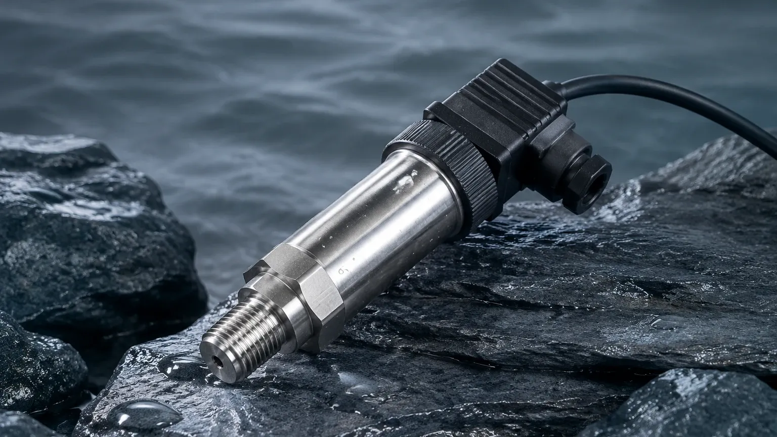
In deep wells, water towers, or chemical storage tanks, a submersible heavy duty pressure transducer is lowered to the bottom. The sensor must be vented to the atmosphere via a capillary tube within the cable to compensate for changes in barometric pressure. Without this venting, atmospheric fluctuations could introduce errors of several centimeters in level readings.
Installation and Maintenance Guidelines
To ensure the longevity and accuracy of a heavy duty pressure transducer, specific installation protocols must be followed:
1. Mounting Position: While most transducers are position-insensitive, mounting them horizontally or vertically can prevent the accumulation of sediment on the diaphragm. In steam applications, always use a syphon (pigtail) to protect the sensor from high-temperature vapor.
2. Pressure Snubbers: If the system is prone to rapid pressure pulsations, such as those caused by reciprocating pumps, a pressure snubber should be installed to dampen the spikes before they reach the sensing element.
3. Cable Routing: Signal cables should be kept away from high-voltage power lines to minimize EMI. For submersible models, ensure the breather tube is protected by a desiccant filter to prevent moisture from entering the sensor housing.
4. Zero Calibration: Over time, sensors may experience a slight "zero shift." Regular maintenance should include checking the zero-point output when the sensor is at atmospheric pressure and adjusting the offset in the control system if necessary.
Limitations and Common Failure Modes
Even the most robust heavy duty pressure transducer has limitations. Understanding these risks is essential for risk mitigation:
* Diaphragm Fatigue: Repeated cycling at the extreme upper limit of the pressure range can eventually lead to material fatigue in the diaphragm, resulting in non-linear readings.
* Chemical Incompatibility: While stainless steel is versatile, certain acids (like hydrochloric acid) can cause pitting. In these cases, specialized coatings or exotic alloys are required.
* Thermal Transients: Rapid changes in media temperature can cause temporary measurement errors as the internal components expand at different rates. High-quality transducers include temperature compensation circuits to mitigate this effect, but extreme shocks should still be avoided.
* Moisture Ingress: The most common cause of failure in submersible applications is not the sensor itself, but moisture entering the cable's vent tube, leading to internal corrosion or short circuits.
Frequently Asked Questions (FAQ)
Q: What is the difference between a pressure transducer and a pressure transmitter?
A: In common industrial parlance, a "transducer" often refers to a device with a voltage output (e.g., 0-5V), while a "transmitter" refers to a device with a current output (e.g., 4-20 mA). However, the terms are frequently used interchangeably in B2B contexts.
Q: How do I choose between a flush diaphragm and a recessed diaphragm?
A: Use a flush diaphragm for viscous fluids, slurries, or media that contains particulates that could clog a standard pressure port. For clean liquids or gases, a standard recessed diaphragm is usually more cost-effective.
Q: Can a heavy duty pressure transducer be used for vacuum measurement?
A: Yes, but you must specify a compound range (e.g., -1 to +10 bar) or an absolute pressure sensor. Standard gauge sensors are designed for positive pressure and may not provide accurate or safe readings under vacuum conditions.
Q: How often should these sensors be recalibrated?
A: For most industrial applications, an annual calibration check is recommended. However, in critical safety systems or highly corrosive environments, semi-annual checks may be necessary to ensure compliance with quality standards.
Conclusion
The selection of a heavy duty pressure transducer is a foundational decision in industrial process design. By understanding the measurement principles—whether piezoresistive or strain-gauge—and strictly adhering to installation best practices, engineers can ensure reliable data collection in the most demanding environments. For professionals seeking to integrate these sensors into broader automation frameworks, reviewing the various technical configurations on the Main Page is a recommended next step to align hardware capabilities with project requirements.