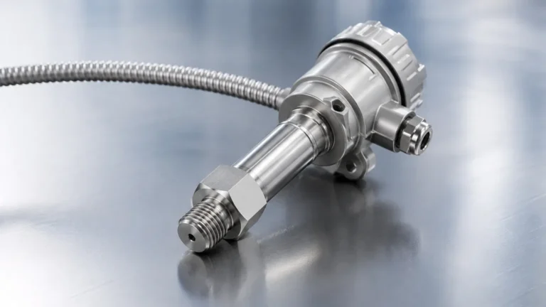
Lift Station Wastewater
Lift Station Wastewater
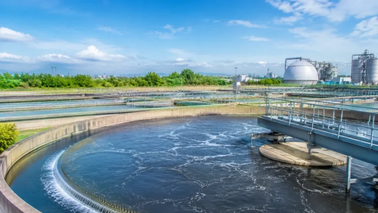
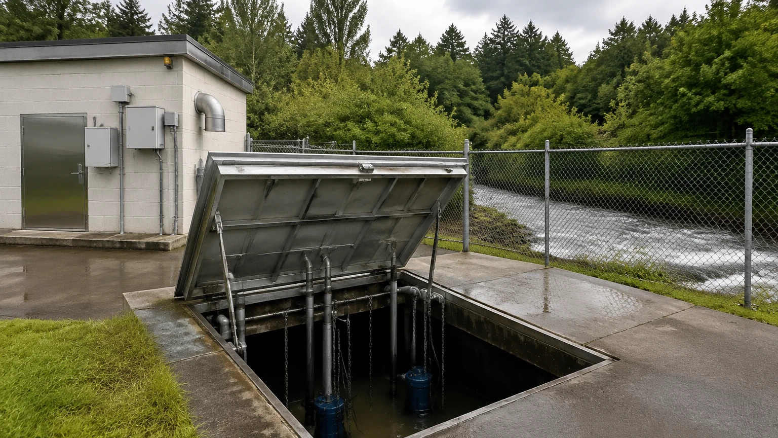
In municipal and industrial infrastructure, the management of lift station wastewater represents one of the most challenging environments for process automation. Lift stations, also known as wet wells or pump stations, are designed to move wastewater from lower to higher elevations when gravity-fed piping is either impractical or cost-prohibitive. Because these stations operate in harsh conditions involving corrosive gases, turbulent inflows, and heavy solids, the selection of level measurement instrumentation is critical to preventing pump dry-run, overflows, and environmental non-compliance.
Reliable level monitoring ensures that pumps activate and deactivate at precise intervals, optimizing energy consumption and extending the service life of the equipment. This article provides a technical overview of the measurement principles, selection criteria, and installation best practices for level sensors in wastewater lift stations.
Measurement Principles for Wastewater Lift Stations
Effective level control in a lift station requires an understanding of how different technologies interact with the fluid surface and the surrounding atmosphere. The following principles are the industry standards for managing lift station wastewater.
1. Ultrasonic Level Measurement (Non-Contact)
Ultrasonic sensors function by emitting high-frequency sound pulses toward the wastewater surface. The sensor measures the time it takes for the echo to return after hitting the liquid. Since the speed of sound in air is known, the internal electronics calculate the distance to the liquid level.
* Advantages: As a non-contact method, the sensor is not subject to corrosion or fouling from the wastewater itself. It is relatively easy to install and calibrate.
* Limitations: Ultrasonic waves can be scattered by heavy foam or absorbed by thick steam. In deep wet wells, temperature gradients can affect the speed of sound, requiring sensors with integrated temperature compensation.
2. Hydrostatic Pressure Measurement (Contact)
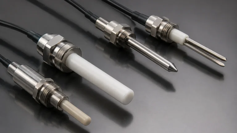
Hydrostatic level transmitters are submerged at the bottom of the lift station. They measure the pressure exerted by the column of liquid above the sensor head. This pressure is directly proportional to the liquid height (P = ρgh).
* Advantages: This method is unaffected by surface foam, floating debris, or turbulence. It provides a continuous, linear signal even in narrow or crowded wet wells.
* Limitations: Sensors are in constant contact with the wastewater. Over time, grease, fats, and oils (FOG) can build up on the diaphragm, leading to measurement drift or failure if not cleaned regularly.
3. Radar Level Measurement (Non-Contact)
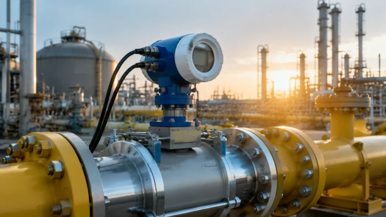
Radar transmitters utilize high-frequency microwave pulses (typically in the 26 GHz or 80 GHz range). Similar to ultrasonic sensors, they measure the time-of-flight of the pulse. However, microwaves are unaffected by air temperature, pressure, or the presence of vapors and gases.
* Advantages: Radar is the most robust non-contact technology. It can penetrate foam to a certain degree and is immune to the corrosive hydrogen sulfide (H2S) gas often found in lift station wastewater.
* Limitations: Radar units generally carry a higher initial capital cost compared to ultrasonic or hydrostatic options.
4. Point Level Switches (Floats)
Float switches are mechanical devices that rise and fall with the water level. When the float reaches a specific angle, an internal microswitch or ball-actuated switch triggers a signal. In lift stations, these are primarily used for high-level and low-level redundant alarms.
Technical Selection Criteria
When evaluating instrumentation for lift station wastewater, engineers must consider several variables to ensure long-term reliability. The following table compares the primary continuous measurement technologies used in the industry.
Technology Comparison Table
| Feature | Ultrasonic Sensors | Radar Level Meters | Hydrostatic Transmitters |
| :— | :— | :— | :— |
| Measurement Type | Non-contact (Sound) | Non-contact (Microwave) | Contact (Pressure) |
| Accuracy | ±0.25% of range | ±2 mm to ±5 mm | ±0.1% to ±0.5% FS |
| Foam Resistance | Poor to Moderate | Good | Excellent |
| FOG Sensitivity | None | None | High (requires cleaning) |
| H2S Resistance | Good (if sealed) | Excellent | Requires specialized cables |
| Installation | Top-mounted | Top-mounted | Submerged/Bottom-mounted |
| Typical Range | 0.3 m to 15 m | 0.1 m to 30 m+ | 1 m to 100 m |
Key Evaluation Factors
1. Chemical Compatibility: Wastewater often contains hydrogen sulfide (H2S), which converts to sulfuric acid in the presence of moisture. Sensors must be constructed from corrosion-resistant materials such as PVDF, PTFE, or high-grade stainless steel (316L). For hydrostatic sensors, the cable jacket should be made of polyurethane (PUR) or FEP.
2. Solids and Grease Content: If the wastewater has high concentrations of fats, oils, and grease (FOG), non-contact sensors (Radar/Ultrasonic) are preferred to avoid frequent maintenance of submerged diaphragms.
3. Turbulence and Inflow: If the sensor is mounted near the influent pipe, the surface will be turbulent. Radar is generally more capable of filtering out signal noise caused by surface agitation than ultrasonic sensors.
Installation Considerations for Lift Stations
Proper installation is as important as selecting the right technology. Poor placement can lead to false readings and pump cycling issues.
Positioning and Mounting
* Avoid Inflow Streams: Never mount a level sensor directly above or near the influent pipe. The falling water creates turbulence and air entrainment that will disrupt ultrasonic and radar signals or create localized pressure spikes for hydrostatic sensors.
* Dead Zone Management: Every non-contact sensor has a "dead zone" (blocking distance) near the face of the transducer. Ensure the sensor is mounted high enough so that the maximum water level never enters this zone.
* Stilling Wells: In extremely turbulent lift stations, a stilling well (a vertical pipe with vent holes) can be used to provide a calm surface for measurement. For hydrostatic sensors, a stilling well prevents the sensor from swinging like a pendulum due to water movement.
Wiring and Signal Integration
Most modern lift stations utilize a 4-20 mA DC signal with HART protocol for integration into a Programmable Logic Controller (PLC) or a Remote Terminal Unit (RTU). For smart city applications, RS485 (Modbus) or wireless IoT outputs are increasingly common. Ensure that all cabling is properly shielded and that surge protection is installed, as lift stations are often located in areas prone to lightning strikes.
Operational Limitations and Common Risks
Despite advances in technology, certain environmental factors remain persistent risks in wastewater management:
* Grease Encapsulation: In hydrostatic systems, grease can harden over the sensor diaphragm, effectively "locking" the pressure reading. This can lead to a pump failing to turn on (overflow) or failing to turn off (pump burnout).
* Signal Absorption: In very deep wet wells, heavy condensation on an ultrasonic transducer face can attenuate the signal. Sensors with "self-cleaning" or vibrating faces are designed to mitigate this.
* Corrosive Off-Gassing: H2S gas is not only toxic but highly corrosive to electronics. Any sensor used in a lift station must have an IP68 ingress protection rating and sealed housings to prevent gas from reaching the internal circuitry.
Frequently Asked Questions (FAQ)
Q: How often should level sensors in lift stations be calibrated?
A: For non-contact sensors, a yearly check is usually sufficient unless there has been a significant change in the process. Hydrostatic sensors may require bi-annual inspection to check for grease buildup and to verify zero-point calibration.
Q: Can radar sensors see through foam in a wet well?
A: High-frequency radar (80 GHz) is better at penetrating foam than ultrasonic sensors, but extremely thick, dense foam can still attenuate the signal. In cases of persistent heavy foam, hydrostatic pressure sensors are the most reliable option.
Q: What is the benefit of using redundant level control?
A: In lift station wastewater management, redundancy is a safety requirement. Most engineers use a continuous transmitter (Radar or Ultrasonic) for primary control and a mechanical float switch for a high-level backup alarm to prevent environmental spills.
Q: Are ultrasonic sensors affected by the methane gas in sewers?
A: Yes, methane and other gases can change the density of the air in the wet well, which slightly alters the speed of sound. This can lead to small measurement errors. Radar is unaffected by gas composition.
Conclusion and Next Steps
Selecting the right level measurement solution for lift station wastewater requires a balance between initial cost, maintenance requirements, and the specific characteristics of the waste stream. While ultrasonic sensors remain a popular cost-effective choice, radar technology is becoming the standard for high-reliability applications due to its immunity to vapors and foam. For those managing deep wells with heavy debris, hydrostatic transmitters offer a rugged, submerged alternative.
Before finalizing an instrument specification, site operators should confirm the maximum expected fluid temperature, the presence of FOG, and the specific communication protocols required by their SCADA system. For more detailed technical specifications and product comparisons, you can Review product options and application support to find the ideal fit for your infrastructure requirements.