Analog Flowmeter
Analog Flowmeter
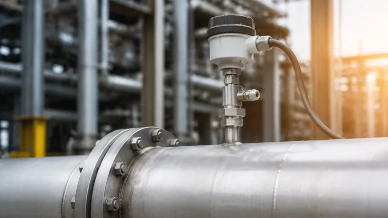
In the landscape of industrial process control, the analog flowmeter remains a cornerstone for monitoring and managing fluid dynamics. Despite the rise of digital protocols, analog systems—primarily those utilizing 4-20mA current loops—continue to be favored for their simplicity, reliability, and real-time response. An analog flowmeter is defined as a device that measures the linear, non-linear, or volumetric flow rate of a liquid or gas and provides a continuous electrical output signal proportional to that flow. This guide explores the fundamental principles, selection criteria, and engineering considerations essential for integrating these instruments into modern industrial environments.
Measurement Principles of Common Flowmeter Technologies
Before selecting an analog flowmeter, it is critical to understand the physical principles governing fluid measurement. Different technologies are suited to specific fluid properties and environmental conditions.
Differential Pressure (DP) Flowmeters
Differential pressure is one of the most established methods for flow measurement. It operates on Bernoulli’s principle, which states that as the speed of a moving fluid increases, the pressure within the fluid decreases. By placing a primary element—such as an orifice plate, Venturi tube, or flow nozzle—inside a pipe, a pressure drop is created. The analog flowmeter then measures the pressure difference between the upstream and downstream sides. The square root of this pressure difference is proportional to the flow rate. These systems are robust but require careful maintenance of impulse lines to prevent clogging.
Electromagnetic Flowmeters (Magmeters)
Electromagnetic flowmeters operate based on Faraday’s Law of Electromagnetic Induction. This law states that a conductor moving through a magnetic field produces an electrical signal. In this application, the conductive liquid (such as water or chemicals) acts as the conductor. As the fluid flows through a magnetic field generated by the meter’s coils, a voltage is induced proportional to the velocity of the fluid. Because there are no moving parts or obstructions in the flow path, magmeters offer very low pressure drop and are ideal for slurries and corrosive liquids, provided the fluid meets a minimum conductivity threshold (typically >5 μS/cm).
Ultrasonic Flowmeters
Ultrasonic technology utilizes sound waves to determine flow velocity. There are two primary types: transit-time and Doppler. Transit-time meters send ultrasonic pulses back and forth across the pipe; the difference in time taken for the pulse to travel with the flow versus against it is used to calculate velocity. Doppler meters, conversely, rely on sound waves reflecting off particles or bubbles in the fluid. These are often available as clamp-on units, allowing for non-intrusive measurement without cutting into existing piping.
Vortex Flowmeters
Vortex meters utilize the Von Kármán effect. When a fluid passes a "shedder bar" or bluff body, vortices are shed alternately on each side. The frequency at which these vortices are shed is directly proportional to the fluid velocity. A sensor (often a piezoelectric crystal) detects these pressure fluctuations and converts them into an analog signal. Vortex meters are highly versatile, capable of measuring liquids, gases, and steam over a wide range of temperatures and pressures.
The Role of Analog Signals in Flow Measurement
The "analog" aspect of these flowmeters refers to the output signal sent to a Programmable Logic Controller (PLC) or Distributed Control System (DCS). While several standards exist, the 4-20mA current loop is the industry benchmark.
* 4-20mA Current Loop: In this configuration, a 4mA signal represents the zero-flow condition (0% of scale), and a 20mA signal represents the maximum flow (100% of scale). This "live zero" at 4mA allows the system to distinguish between a zero-flow state and a wire break (0mA). Current signals are also less susceptible to electromagnetic interference (EMI) and voltage drops over long cable runs compared to voltage signals.
* 0-10V Voltage Signal: While easier to test with a standard multimeter, voltage signals are prone to degradation over long distances due to wire resistance and are more sensitive to electrical noise. They are typically reserved for localized equipment or HVAC applications.
For engineers looking to integrate these devices into comprehensive monitoring systems, reviewing the latest Main Page resources can provide insights into how flow data correlates with other process variables like tank levels and pressure.
Selection Criteria for an Analog Flowmeter
Selecting the correct instrument requires a detailed analysis of the application's physical and chemical parameters. Failure to account for these can lead to measurement inaccuracies or premature equipment failure.
Fluid Properties
* Conductivity: Essential for electromagnetic meters. Non-conductive fluids like oils or deionized water require ultrasonic or vortex technologies.
* Viscosity: High-viscosity fluids can affect the Reynolds number, potentially impacting the accuracy of vortex and DP meters.
* Corrosivity: Ensure that the wetted parts (electrodes, liners, or shedder bars) are compatible with the chemical composition of the fluid. Common materials include SS316L, Hastelloy, and PTFE liners.
Process Conditions
* Temperature and Pressure: Every analog flowmeter has specific ratings. For high-temperature steam applications, vortex meters are often preferred over ultrasonic units.
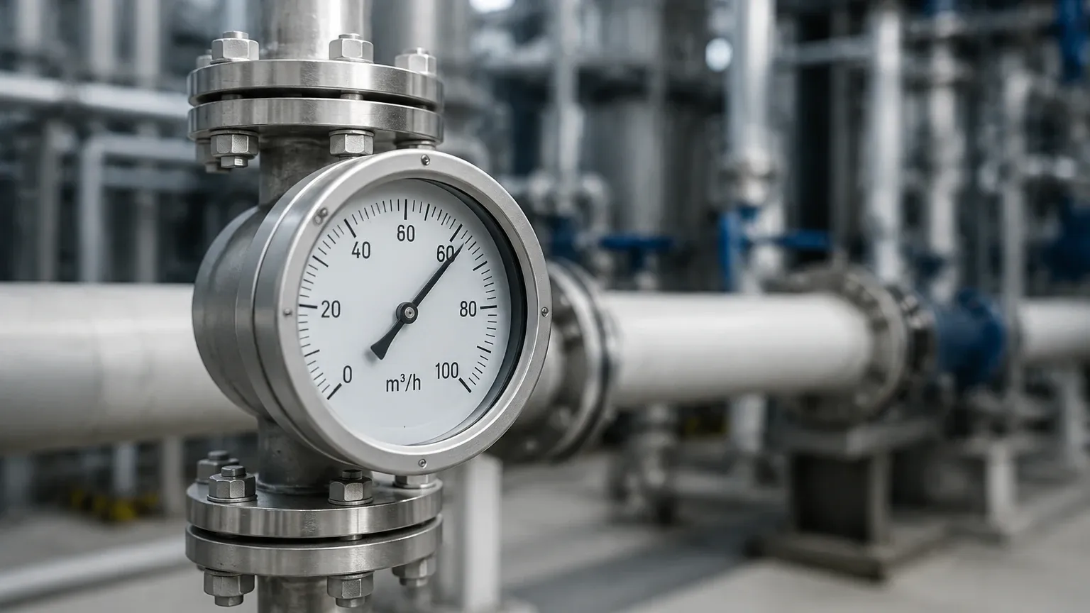
* Flow Range (Turndown Ratio): The turndown ratio defines the range over which the meter can measure accurately. For example, a 10:1 ratio means a meter with a maximum capacity of 100 m³/h can accurately measure down to 10 m³/h.
Accuracy and Repeatability
In B2B industrial environments, accuracy is often expressed as a percentage of the actual reading or a percentage of the full-scale (FS) value. For custody transfer or precise chemical dosing, high-accuracy electromagnetic or Coriolis meters (which can also output analog signals) are necessary.
Technical Comparison Table: Analog Flowmeter Technologies
| Technology | Typical Accuracy | Fluid Suitability | Pressure Drop | Moving Parts | Maintenance Level |
| :— | :— | :— | :— | :— | :— |
| Differential Pressure | ±0.5% to ±2% | Liquid, Gas, Steam | Medium to High | No | Medium (Impulse lines) |
| Electromagnetic | ±0.2% to ±0.5% | Conductive Liquids | Negligible | No | Low |
| Ultrasonic | ±1% to ±2% | Clean Liquids | None | No | Low |
| Vortex | ±0.75% to ±1.5% | Liquid, Gas, Steam | Low to Medium | No | Low |
| Variable Area | ±1% to ±5% | Liquid, Gas | Low | Yes | Medium |
Installation Considerations and Best Practices
Proper installation is as important as instrument selection. Even the most accurate analog flowmeter will provide unreliable data if installed incorrectly.
1. Straight Pipe Runs: Most flowmeters require a specific length of straight pipe upstream and downstream to ensure a stable, laminar flow profile. A common rule of thumb is "10D Upstream and 5D Downstream," where D is the internal diameter of the pipe. If elbows, valves, or pumps are close to the meter, these requirements may increase to 20D or 30D.
2. Pipe Orientation: For liquid applications, the pipe must remain full at all times. Vertical installation with upward flow is often recommended to prevent air pockets. For horizontal runs, the meter should not be placed at the highest point of the piping system where air can collect.
3. Grounding: For electromagnetic flowmeters, proper grounding is non-negotiable. The fluid, the meter body, and the adjacent piping must be at the same electrical potential to prevent stray currents from interfering with the small millivolt signals generated by the sensors.
4. Signal Shielding: To maintain the integrity of the 4-20mA analog signal, use twisted-pair shielded cables. Ensure the shield is grounded at only one end (usually the PLC/DCS end) to prevent ground loops.
Limitations and Potential Risks
While analog flowmeters are dependable, they are not without limitations. Engineers should be aware of the following risks:
* Signal Interference: High-voltage equipment, variable frequency drives (VFDs), and heavy machinery can generate EMI. If analog signal cables are run parallel to power lines without proper shielding, the flow data may fluctuate or become offset.
* Zero Drift: Over time, the analog output may drift, meaning the 4mA signal no longer represents exactly zero flow. Periodic calibration and zero-point adjustment are required to maintain system integrity.
* Cavitation and Flashing: In liquid systems, if the local pressure drops below the vapor pressure, bubbles form (cavitation). This can damage the internal components of vortex or DP meters and cause significant measurement errors.
* Environmental Factors: For outdoor installations, extreme temperatures can affect the electronics of the transmitter. In such cases, sunshades or heated enclosures may be necessary to keep the instrument within its operating temperature range (typically -20°C to +60°C for the electronics).
Frequently Asked Questions (FAQs)
Q: Can an analog flowmeter be used for gas measurement?
A: Yes, vortex and differential pressure meters are frequently used for gas and steam. However, because gases are compressible, the analog signal usually represents the "actual" flow rate. To obtain the "standard" flow rate, pressure and temperature compensation are required.
Q: What is the maximum distance for a 4-20mA analog signal?
A: Depending on the wire gauge and the power supply voltage, a 4-20mA signal can typically travel up to 1,000 meters without significant degradation, making it ideal for large industrial sites.
Q: How often should an analog flowmeter be calibrated?
A: Calibration frequency depends on the criticality of the process and the fluid's characteristics. For most industrial applications, an annual calibration check is standard. Highly corrosive or abrasive applications may require quarterly inspections.
Conclusion
The analog flowmeter remains a vital tool in the industrial engineer's arsenal. By understanding the underlying physics—whether it be electromagnetic induction, vortex shedding, or differential pressure—and adhering to strict installation guidelines, facilities can ensure accurate and reliable process monitoring. While digital transformation continues to evolve, the robustness and simplicity of the 4-20mA analog interface ensure that these instruments will remain relevant for decades to come. For those managing complex systems that involve both fluid movement and storage, integrating flow data with reliable level measurement solutions is the next step toward optimized automation. To explore a wider range of measurement technologies and technical support, professionals are encouraged to Review product options and application support to find the most suitable configuration for their specific industrial needs.