High Pressure Flow Meters
High Pressure Flow Meters
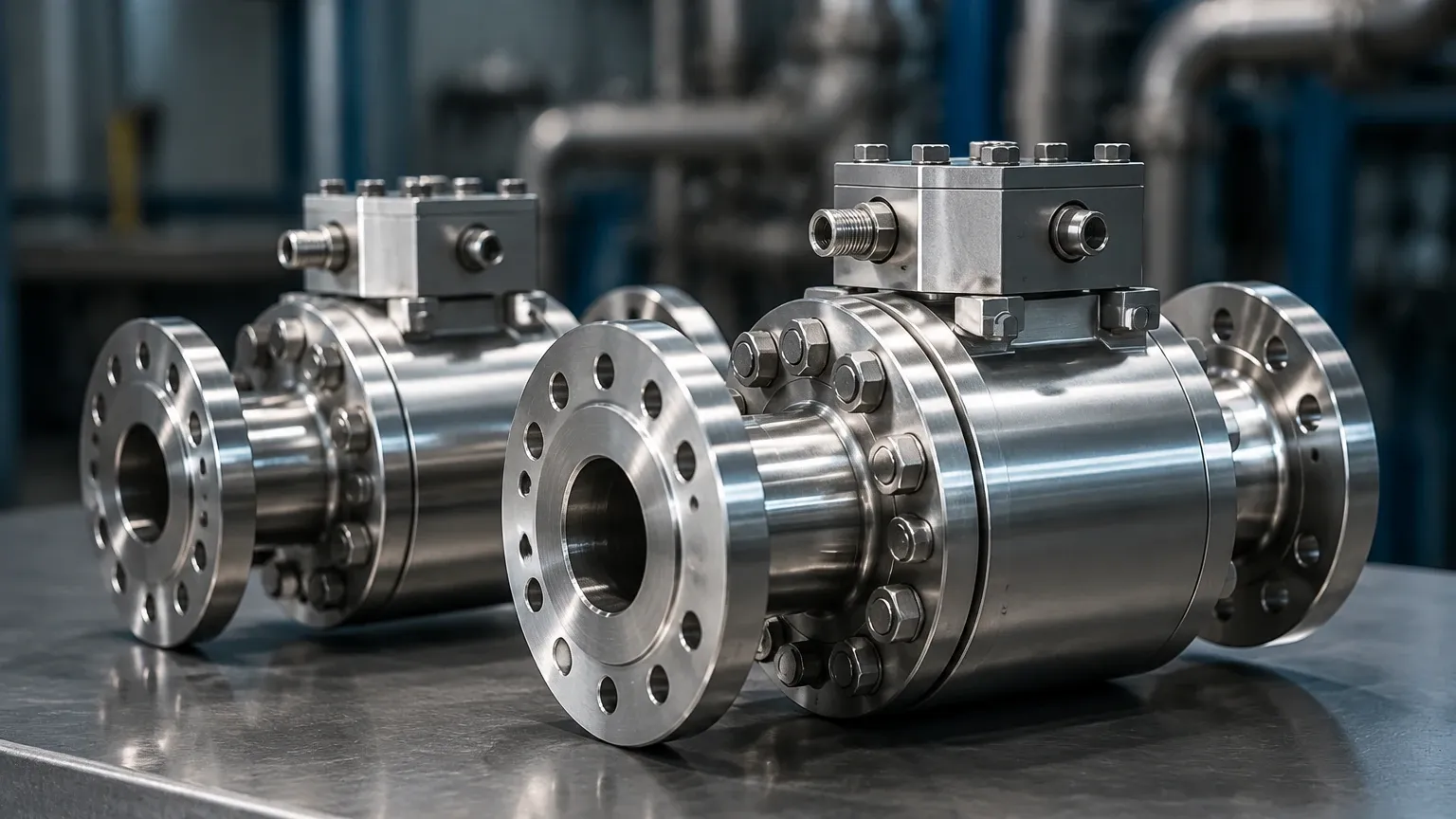
In industrial process control, the measurement of fluid flow under high-pressure conditions presents a unique set of engineering challenges. High pressure flow meters are specialized instruments designed to operate reliably in environments where standard sensors would fail due to mechanical stress, leakage, or material fatigue. Typically defined as applications exceeding 100 bar (1,450 psi) and reaching up to 1,000 bar (14,500 psi) or more, these systems are critical in sectors such as oil and gas extraction, chemical synthesis, hydraulic power units, and high-pressure water jetting.
Selecting the correct instrumentation requires a deep understanding of fluid dynamics under compression and the mechanical integrity of the meter housing. This guide explores the fundamental measurement principles, selection criteria, and installation best practices for high-pressure flow measurement.
Measurement Principles for High-Pressure Environments
Before selecting a specific meter, engineers must evaluate how the measurement technology interacts with the fluid under high static pressure. The following principles are the most common in high-pressure applications.
1. Differential Pressure (DP) Flow Meters
Differential pressure remains one of the most established methods for high-pressure measurement. It relies on Bernoulli’s principle, which states that as the speed of a moving fluid increases, the pressure within the fluid decreases. By placing a restriction in the pipe—such as an orifice plate, Venturi tube, or Pitot tube—a pressure drop is created. The square root of this pressure difference is proportional to the flow rate.
In high-pressure systems, the primary challenge for DP meters is the integrity of the pressure-sensing lines and the transmitter’s ability to withstand high static pressure while measuring a very small differential. Heavy-walled manifolds and specialized seals are required to prevent catastrophic failure.
2. Coriolis Mass Flow Meters
Coriolis meters measure mass flow directly by detecting the inertia created by fluid flowing through vibrating tubes. As the fluid moves through the oscillating tubes, it causes a slight twist (Coriolis effect) proportional to the mass flow rate.
For high-pressure service, Coriolis meters use thick-walled measuring tubes. While this increases the weight and cost of the instrument, it provides exceptional accuracy (often better than 0.1%) and the ability to measure mass flow regardless of changes in fluid density or viscosity caused by pressure fluctuations. They are widely used in high-pressure chemical injection and CNG (Compressed Natural Gas) dispensing.
3. Turbine Flow Meters
Turbine meters utilize a rotor suspended in the fluid stream. The velocity of the fluid causes the rotor to spin at a rate proportional to the flow volume. Magnetic pickups or modulated carrier sensors detect the blade passes through the high-pressure housing without requiring a physical penetration that could leak.
High pressure flow meters using turbine technology must be designed with robust bearings—often tungsten carbide or ceramic—to handle the increased fluid density and potential axial thrust. They are highly effective for clean, low-viscosity liquids like water, solvents, and light oils.
4. Ultrasonic (Transit-Time) Flow Meters
Ultrasonic meters measure the difference in time it takes for an ultrasonic pulse to travel upstream versus downstream. Because sound travels faster with the flow and slower against it, the time difference is proportional to the fluid velocity.
In high-pressure applications, ultrasonic meters are often preferred because they can be designed with "wetted" transducers that do not obstruct the flow path or "clamp-on" sensors that sit outside the pipe. For extremely high pressures, wetted transducers are typically housed in specialized high-strength plugs to ensure a leak-proof seal.
5. Positive Displacement (PD) Flow Meters
PD meters, such as gear or piston meters, trap a fixed volume of fluid and move it through the meter. The number of rotations or cycles is counted to determine the total flow. These are excellent for high-viscosity fluids at high pressure, such as hydraulic oils. The tight tolerances required for PD meters mean they are sensitive to particulates, but they offer high repeatability in high-pressure hydraulic circuits.
Technical Selection Criteria
Choosing between these technologies requires a systematic review of the process parameters. The table below provides a general comparison of common high-pressure flow measurement technologies.
| Technology | Typical Max Pressure | Accuracy | Fluid Type | Primary Advantage |
| :— | :— | :— | :— | :— |
| Differential Pressure | 400+ bar | 1.0% – 2.0% | Gas / Liquid | Robust, no moving parts |
| Coriolis | 1,000+ bar | 0.1% – 0.5% | Gas / Liquid | Direct mass flow measurement |
| Turbine | 700 bar | 0.25% – 0.5% | Clean Liquids | High resolution, fast response |
| Ultrasonic | 600+ bar | 0.5% – 1.0% | Gas / Liquid | No pressure drop, wide turndown |
| Positive Displacement | 1,000+ bar | 0.5% | Viscous Liquids | High pressure/viscosity capability |
Material Compatibility and Safety Factors
At high pressures, the "hoop stress" on the meter body is significant. Materials must be selected not only for chemical compatibility but also for tensile strength and resistance to hydrogen embrittlement or stress corrosion cracking. Common materials include:
- 316/316L Stainless Steel: Standard for moderate high pressure and corrosion resistance.
- Duplex/Super Duplex Stainless Steel: Used for higher strength and seawater resistance.
- Hastelloy C276: For extremely corrosive high-pressure chemical applications.
- Titanium: Used where weight reduction and high strength-to-weight ratios are required.
Engineers must also verify the Safety Factor. Most industrial standards (such as ASME B31.3) require the burst pressure of the meter body to be at least four times the maximum operating pressure.
Installation Considerations for High-Pressure Systems
Proper installation is paramount for both measurement accuracy and personnel safety. High-pressure leaks can be lethal, and even minor installation errors can lead to instrument failure.
1. Seal Selection: Traditional NPT threads are often insufficient for pressures above 10,000 psi (690 bar). Instead, use autoclaved fittings, medium/high-pressure cone-and-thread connections, or specialized ring-type joint (RTJ) flanges.
2. Straight Pipe Runs: Like all flow meters, high pressure flow meters require stable flow profiles. Ensure adequate straight pipe diameters (typically 10D upstream and 5D downstream) to prevent turbulence from valves or elbows from affecting the reading.
3. Vibration Damping: High-pressure pumps (such as reciprocating plunger pumps) create significant pulsations. These pulsations can cause "noise" in Coriolis and DP meters. Installing pulsation dampeners or using meters with high-frequency digital filtering is necessary.
4. Orientation: For gas applications, install meters in a horizontal run to prevent moisture buildup. For liquids, ensure the meter is at a low point or in a vertical "up" flow orientation to keep the meter full of liquid and prevent air pockets.
5. Bypass Manifolds: Always install a three-valve or five-valve manifold. This allows the meter to be isolated for maintenance or zero-calibration without shutting down the entire high-pressure process line.
Operational Limitations and Risks
While high-pressure meters are built for durability, they are not immune to environmental and process-related risks:
- Pressure Spikes: Rapid opening of valves can cause water hammer or pressure surges that exceed the meter's design limit. Slow-acting valves or surge tanks are recommended.
- Fluid Compressibility: In high-pressure gas measurement, the gas becomes highly compressed and deviates from the ideal gas law. Real gas factors (Z-factors) must be programmed into the flow computer to maintain accuracy.
- Erosion: High-velocity fluids carrying even small amounts of solids can erode the internal components of turbine or DP meters. Hardened coatings or upstream filtration are essential.
- Thermal Expansion: High pressure often correlates with high temperature. The expansion of the meter body can change the internal volume or the distance between ultrasonic transducers, requiring temperature compensation algorithms.
For industrial facilities managing complex fluid systems, flow measurement is only one part of the equation. Integrating these sensors with accurate level monitoring—such as radar or ultrasonic level sensors—is necessary for mass balance and inventory control. To explore a wider range of industrial measurement instruments, users can Review product options and application support on the Welk Main Page.
Frequently Asked Questions (FAQ)
How often should high pressure flow meters be calibrated?
Calibration frequency depends on the fluid's abrasiveness and the criticality of the measurement. For fiscal billing or high-accuracy chemical injection, annual calibration is standard. For general process monitoring, every two years may suffice, provided there is no evidence of drift.
Can I use a standard flow meter for high-pressure water jetting?
No. Standard flow meters are typically rated for PN16 or PN40 (approx. 230-580 psi). Water jetting often operates at 1,000 to 4,000 bar. Using a standard meter in these conditions will result in immediate mechanical failure and poses a severe safety risk.
Do high-pressure meters require special cleaning?
In oxygen service or high-purity chemical applications, meters must be cleaned to specific standards (e.g., ASTM G93) to remove hydrocarbons. At high pressures, even trace amounts of oil can lead to spontaneous combustion in oxygen-rich environments.
What is the difference between "Operating Pressure" and "Design Pressure"?
Operating pressure is the typical pressure the meter sees during normal production. Design pressure (or MAWP – Maximum Allowable Working Pressure) is the highest pressure the meter can safely handle continuously. Always ensure your process relief valves are set below the meter's design pressure.
Conclusion
High pressure flow meters are essential for the safe and efficient operation of modern industrial processes. By understanding the underlying measurement principles—whether it be the mass-sensing capabilities of a Coriolis meter or the non-intrusive nature of ultrasonic technology—engineers can select a solution that balances accuracy, safety, and cost. Proper material selection and adherence to rigorous installation standards ensure that these instruments provide reliable data even in the most demanding high-pressure environments.