Flow Meters for Natural Gas
Flow Meters for Natural Gas
In industrial automation and process engineering, the accurate measurement of natural gas flow is a fundamental requirement for operational efficiency, safety, and fiscal accountability. Natural gas, primarily composed of methane, presents unique challenges due to its compressibility, varying composition, and the high-pressure environments in which it is typically transported. Selecting the appropriate flow meters for natural gas requires a deep understanding of fluid dynamics, gas properties, and the specific requirements of the application, whether it involves burner control, industrial heating, or custody transfer.
This guide examines the primary measurement principles utilized in gas flow technology, provides selection criteria for engineering teams, and outlines the critical installation factors that ensure long-term reliability in the field.
Measurement Principles for Natural Gas Flow
Before selecting an instrument, it is essential to understand the physical principles governing how different meters interact with gas. Natural gas flow measurement is generally categorized into volumetric flow and mass flow measurement.
Differential Pressure (DP) Measurement
Differential pressure flow meters operate on Bernoulli’s principle, which states that an increase in the velocity of a fluid occurs simultaneously with a decrease in pressure. In these systems, a primary element—most commonly an orifice plate—is inserted into the pipeline to create a constriction. As the natural gas passes through the orifice, the pressure drops. This pressure difference ($ΔP$) is measured by a transmitter and is proportional to the square of the flow rate. While robust and standardized (ISO 5167), DP meters introduce a permanent pressure loss in the system.
Turbine Flow Measurement
Turbine meters utilize the kinetic energy of the flowing gas to rotate a multi-bladed rotor. The angular velocity of the rotor is proportional to the gas velocity. These meters are widely used in high-pressure transmission lines and distribution networks. They offer excellent repeatability but contain moving parts that are susceptible to wear if the gas contains particulates or "black powder" (corrosion byproducts).
Ultrasonic Transit-Time Measurement
Ultrasonic flow meters use acoustic signals to determine flow velocity. Transducers are mounted on opposite sides of the pipe, sending pulses back and forth. The time difference between the pulse traveling with the flow and the pulse traveling against the flow is used to calculate the velocity. Because they have no moving parts and do not obstruct the flow path, they are increasingly preferred for large-diameter pipelines and high-accuracy custody transfer applications.
Thermal Mass Flow Measurement
Thermal mass meters operate based on the convective heat transfer from a heated surface to the flowing gas. Two sensors are used: one serves as a reference, and the other is heated. The gas flow carries heat away from the heated sensor, and the power required to maintain a constant temperature difference is proportional to the mass flow rate. This technology is particularly effective for low-pressure applications and detecting leaks because it measures mass flow directly without needing separate pressure and temperature compensation.
Coriolis Mass Flow Measurement
Coriolis meters measure the mass flow rate by detecting the inertia of the gas as it flows through vibrating tubes. As the gas moves, it causes a phase shift in the tube's vibration, which is directly proportional to the mass flow. While highly accurate and capable of measuring gas density, Coriolis meters can be cost-prohibitive for very large pipe diameters.
Criteria for Selecting Flow Meters for Natural Gas
Choosing the right technology involves balancing accuracy requirements against installation constraints and budget. Engineers should evaluate the following parameters:
1. Process Conditions: Operating pressure (bar or PSI) and temperature (°C or °F) significantly affect gas density. High-pressure applications often favor turbine or ultrasonic meters.
2. Turndown Ratio: This is the ratio of the maximum flow to the minimum flow that the meter can accurately measure. If a facility has highly variable demand, a high turndown ratio (e.g., 100:1 for thermal mass) is required.
3. Accuracy and Repeatability: For internal process monitoring, an accuracy of ±1.5% to ±2% may suffice. However, for custody transfer (where gas is bought or sold), accuracies of ±0.5% or better are mandatory.
4. Gas Quality: If the natural gas is "wet" (containing liquids or condensates) or "sour" (containing $H_2S$), the meter materials must be compatible, and the measurement principle must be resilient to liquid entrainment.
Technology Comparison Table
| Technology | Typical Accuracy | Turndown Ratio | Pressure Drop | Moving Parts | Primary Application |
| :— | :— | :— | :— | :— | :— |
| Orifice Plate | ±1.0% – 2.0% | 3:1 to 4:1 | High | No | General industrial use |
| Turbine | ±0.5% – 1.0% | 10:1 to 20:1 | Medium | Yes | Distribution/Transmission |
| Ultrasonic | ±0.1% – 0.5% | 50:1 or higher | Negligible | No | Custody Transfer/Large pipes |
| Thermal Mass | ±1.0% | 100:1 | Low | No | Low pressure/Leak detection |
| Coriolis | ±0.1% – 0.5% | 20:1 | Medium | No | High-value mass measurement |
Installation and Engineering Considerations
Proper installation is as critical as meter selection. Even the most accurate flow meters for natural gas will fail to perform if the flow profile is disturbed.
Straight Pipe Run Requirements
Most flow meters require a specific length of straight pipe upstream and downstream to ensure a fully developed, non-turbulent flow profile. For example, an orifice meter may require 20 to 40 pipe diameters (D) of straight run upstream depending on the presence of elbows or valves. If space is limited, flow conditioners or straightening vanes must be installed to mitigate swirl and turbulence.
Pressure and Temperature Compensation
Since natural gas is highly compressible, its volume changes significantly with pressure and temperature changes. To convert "actual" flow (the volume measured at line conditions) to "standard" or "normal" flow (the volume at a reference pressure and temperature), a flow computer is used. This device integrates inputs from the flow meter, a pressure transmitter, and a temperature sensor (RTD) to calculate the corrected flow rate.
Hazardous Area Classifications
Natural gas is flammable, meaning all instrumentation must comply with local hazardous area regulations (such as ATEX in Europe or Class I, Div 1/2 in North America). Flow meters must be explosion-proof or intrinsically safe to prevent ignition in the event of a gas leak.
Integration with Level Measurement Systems
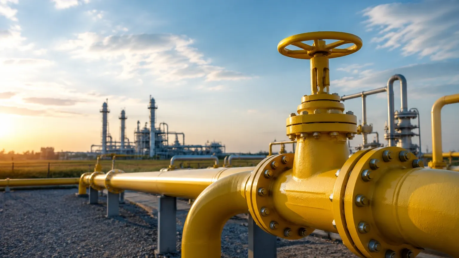
In many natural gas processing plants, flow measurement is closely integrated with level measurement. For instance, in gas-liquid separators, it is vital to monitor the liquid level to prevent "carryover." If the liquid level in a separator rises too high, droplets can enter the gas stream, potentially damaging downstream turbine meters or causing measurement errors in ultrasonic systems.
Welk provides specialized industrial level measurement instruments that complement gas flow systems. Using technologies like radar level meters or magnetic level gauges in separator tanks ensures that the gas entering the flow meter remains within the specified dryness limits. For more information on optimizing your process control, you can Review product options and application support on the Welk Main Page.
Common Risks and Limitations
* Condensation: In "wet gas" applications, liquid droplets can accumulate in low spots of the piping or on the sensor elements. This can cause significant over-reading in DP and turbine meters.
* Vibration: Coriolis and ultrasonic meters can be sensitive to high-frequency vibrations from nearby compressors or pressure-reducing valves. Proper piping support and isolation are necessary.
* Contamination: Particulates in natural gas can erode the sharp edge of an orifice plate or damage the bearings in a turbine meter, leading to a gradual drift in accuracy that may go unnoticed without regular inspection.
Frequently Asked Questions (FAQs)
Q: How often should flow meters for natural gas be calibrated?
A: Calibration frequency depends on the application and local regulations. For custody transfer, annual or semi-annual calibration is common. For internal process monitoring, a check every 2 to 3 years may be sufficient, provided the gas is clean.
Q: Can I use an ultrasonic flow meter for small-diameter pipes?
A: While possible, ultrasonic meters are most cost-effective and accurate in pipe diameters of 100mm (4 inches) and larger. For smaller lines, thermal mass or Coriolis meters are often more practical.
Q: What is the difference between Standard Cubic Meters (Sm³) and Actual Cubic Meters (Am³)?
A: Actual Cubic Meters represent the volume the gas occupies at its current pressure and temperature. Standard Cubic Meters represent the volume that same amount of gas would occupy at a standard reference condition (e.g., 15°C and 1.01325 bar). Most billing and reporting are done in Standard units.
Q: Do thermal mass flow meters require a pressure transmitter?
A: No. One of the primary advantages of thermal mass technology is that it measures the mass flow of the gas directly. Since the heat transfer is related to the number of molecules passing the sensor, it is inherently compensated for pressure and temperature changes.
By carefully evaluating the measurement principle, installation environment, and the need for integrated level control in processing stages, engineers can implement a natural gas flow measurement solution that provides both accuracy and long-term reliability.