Ultrasonic Air Flow Meter
Ultrasonic Air Flow Meter
In modern industrial automation and process control, the precise measurement of gas velocity and volume is essential for energy efficiency, safety, and regulatory compliance. The ultrasonic air flow meter has emerged as a preferred technology for many engineers due to its non-intrusive nature and high reliability. As a professional manufacturer of industrial measurement instruments, Welk provides advanced solutions that leverage ultrasonic technology to address the complexities of gas flow monitoring in environments ranging from clean rooms to heavy industrial exhaust systems.
This guide explores the fundamental principles, selection criteria, and installation best practices for ultrasonic air flow meters, providing a practical engineering reference for technical professionals.
1. Measurement Principles of Ultrasonic Air Flow Meters
Before selecting a specific meter, it is vital to understand the physics governing ultrasonic measurement. Unlike mechanical meters that rely on moving parts, ultrasonic meters use sound waves to determine the velocity of the air or gas moving through a conduit. There are two primary methods used in industrial applications: Transit-Time and Doppler Effect.
Transit-Time Method
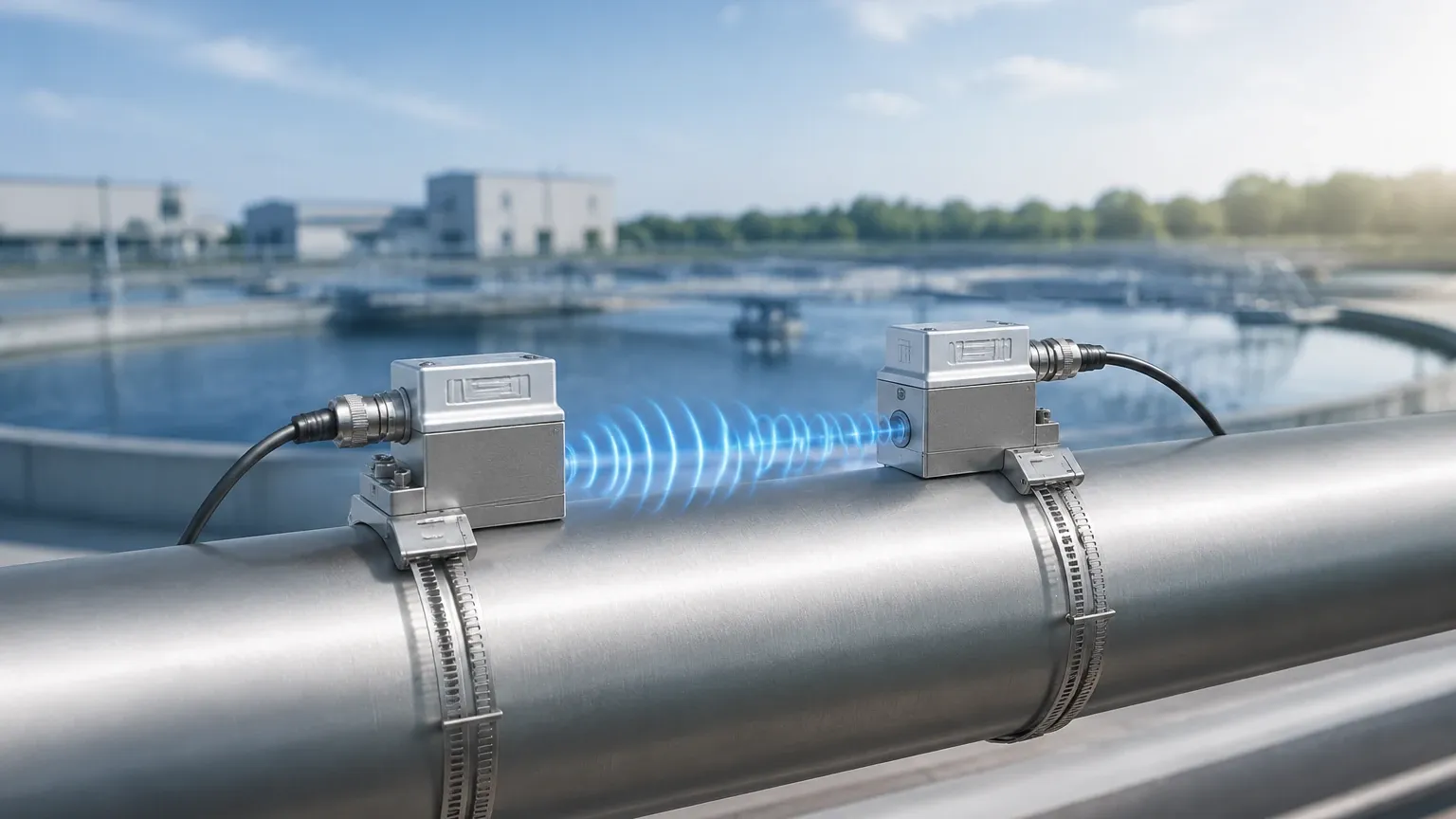
This is the most common principle used for an ultrasonic air flow meter measuring clean gases. The system utilizes a pair of transducers, each acting as both a transmitter and a receiver. One transducer is placed upstream and the other downstream.
1. Downstream Pulse: The upstream transducer sends a pulse to the downstream transducer. Because the sound is traveling with the flow, it moves faster.
2. Upstream Pulse: The downstream transducer sends a pulse to the upstream transducer. Because the sound is traveling against the flow, it moves slower.
3. Time Difference (Δt): The meter calculates the difference in time between these two pulses. This time difference is directly proportional to the velocity of the air.
Mathematically, the velocity (v) is expressed as:
`v = (L / 2cosθ) * (Δt / (t1 * t2))`
Where *L* is the path length, *θ* is the angle of the ultrasonic beam, and *t1/t2* are the transit times.
Doppler Effect Method
The Doppler method is less common for pure air but is utilized when the gas stream contains significant particulate matter or entrained moisture that can reflect sound waves. The meter transmits a sound wave at a known frequency. When this wave hits a moving particle, it reflects back to the receiver with a frequency shift. The magnitude of this shift is proportional to the speed of the particle (and thus the air flow).
2. Key Evaluation Criteria for Industrial Selection
Selecting the right ultrasonic air flow meter requires a thorough analysis of the process conditions. Because gases are compressible and have lower acoustic impedance than liquids, the hardware must be specifically designed for gas applications.
Gas Composition and Density
Ultrasonic signals attenuate (lose strength) much faster in gas than in liquid. The density of the air, influenced by pressure and temperature, affects signal strength. Higher pressure generally improves signal transmission, making ultrasonic meters highly effective for compressed air systems operating at 5 bar (72.5 psi) or higher.
Pipe Diameter and Material
Ultrasonic meters are available in inline and clamp-on configurations.
- Inline Meters: These are integrated into a pipe section (spool piece) and offer the highest accuracy (often ±0.5% to ±1.0%). They are typically used for pipe sizes from DN25 (1 inch) to DN600 (24 inches).
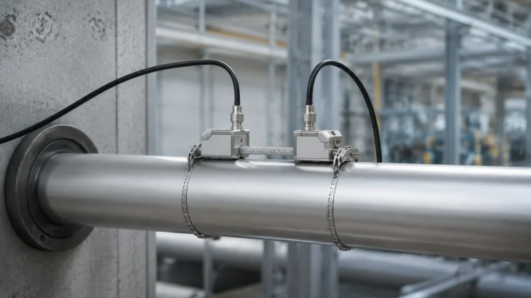
- Clamp-on Meters: These are mounted on the outside of the pipe. While convenient for retrofitting, they require precise knowledge of pipe wall thickness and material to calculate the refraction of the sound wave correctly.
Flow Range and Turndown Ratio
One of the greatest advantages of the ultrasonic air flow meter is its wide turndown ratio, often exceeding 100:1. This allows the meter to capture both low-velocity leaks and high-velocity peak demands without the pressure drop associated with orifice plates or Venturi meters.
3. Practical Selection Table
The following table provides a comparison of typical specifications for ultrasonic air flow meters used in industrial air and gas applications.
| Feature | Transit-Time (Inline) | Transit-Time (Clamp-on) | Thermal Mass (Comparison) |
| :— | :— | :— | :— |
| Typical Accuracy | ±0.5% to ±1.0% of rate | ±1.0% to ±3.0% of rate | ±1.0% to ±2.0% of FS |
| Pipe Size Range | DN25 to DN1000 | DN50 to DN3000 | DN15 to DN6000 |
| Pressure Drop | Negligible | Zero | Low to Moderate |
| Media Requirements | Clean, dry, or wet gas | Clean gas, known pipe specs | Clean, dry gas |
| Installation | Flanged/Welded | External Straps | Insertion/Inline |
| Maintenance | Low (no moving parts) | Very Low | Periodic cleaning required |
For engineers looking to integrate these sensors into broader automation frameworks, reviewing the Main Page of specialized manufacturers like Welk can provide insights into compatible signal outputs (4-20mA, Modbus, HART) and housing ratings (IP67/NEMA 4X).
4. Installation Considerations and Best Practices
The performance of an ultrasonic air flow meter is heavily dependent on the flow profile of the gas. Turbulence caused by elbows, valves, or reducers can lead to measurement errors.
Straight Pipe Run Requirements
To ensure a fully developed laminar flow profile, standard installations typically require:
- Upstream: 10 to 20 diameters (D) of straight pipe.
- Downstream: 5 diameters (D) of straight pipe.
If these distances cannot be met, the use of a flow conditioner or a multi-path ultrasonic meter (which uses multiple beams to average the velocity across the pipe cross-section) is recommended.
Transducer Orientation
For horizontal pipes, transducers should ideally be mounted in the 3 o'clock and 9 o'clock positions. This prevents interference from moisture or condensate settling at the bottom of the pipe and air pockets or sediment at the top.
Signal Interference
Ultrasonic meters can be sensitive to ultrasonic noise generated by certain types of pressure-reducing valves (PRVs). If a PRV is located near the meter, it may be necessary to install the meter further upstream or use acoustic insulation to protect the sensors from high-frequency interference.
5. Limitations and Common Risks
While highly versatile, the ultrasonic air flow meter is not a universal solution for every gas application. Engineers should be aware of the following limitations:
1. Minimum Pressure Requirements: Many clamp-on ultrasonic meters struggle with low-pressure air (near atmospheric pressure) because the acoustic coupling between the transducer, pipe wall, and gas is weak. Inline models with specialized transducers are better suited for low-pressure applications.
2. Gas Velocity Limits: Most ultrasonic meters have a maximum velocity limit (typically around 30-40 m/s). Exceeding this can cause signal "blow away," where the sound pulse is carried so far downstream that it misses the receiving transducer.
3. Cost: Compared to simple thermal mass meters or vortex meters, high-end ultrasonic gas meters represent a higher initial investment, though this is often offset by lower maintenance and zero pressure drop energy savings.
6. Frequently Asked Questions (FAQ)
Q: Can an ultrasonic air flow meter measure compressed air with high moisture content?
A: Yes, but with caveats. While transit-time meters can handle some moisture, excessive liquid droplets can scatter the ultrasonic signal. In high-moisture environments, it is best to install the meter in a vertical pipe section with upward flow or ensure proper trapping and drainage upstream.
Q: How often does an ultrasonic meter need calibration?
A: Because there are no moving parts to wear out and no orifices to erode, ultrasonic meters are extremely stable. Many industrial standards recommend a calibration check every 2 to 5 years, depending on the criticality of the process and local regulations.
Q: Is it possible to use a liquid ultrasonic meter for air flow?
A: Generally, no. The transducers used for liquids operate at different frequencies and power levels than those used for gases. Gas transducers must be designed to overcome the high impedance mismatch between the sensor face and the gas molecules.
7. Conclusion and Next Steps
The ultrasonic air flow meter stands as a pillar of modern industrial measurement, offering a combination of accuracy and low-maintenance operation that mechanical meters cannot match. By understanding the transit-time principle and adhering to strict installation guidelines regarding straight pipe runs and gas density, facilities can achieve significant improvements in process transparency.
When planning a flow measurement project, it is essential to confirm the specific gas composition, operating pressure range, and pipe dimensions. For technical specifications on high-precision instruments and to explore customized OEM/ODM services for industrial automation, engineers are encouraged to visit the Main Page to review product options and application support. Selecting a partner with a robust background in level and flow measurement, such as Welk, ensures that the chosen technology aligns with the long-term operational goals of the facility.