Laser Raman Spectroscopy Instrumentation
Laser Raman Spectroscopy Instrumentation
In the modern industrial landscape, the demand for real-time, non-destructive chemical analysis has led to the widespread adoption of laser Raman spectroscopy instrumentation. Once confined to high-end research laboratories, Raman spectroscopy is now a cornerstone of Process Analytical Technology (PAT), providing deep insights into molecular structures without the need for complex sample preparation. For engineers and plant managers, understanding the mechanics, selection criteria, and integration of these instruments is essential for optimizing production efficiency and ensuring product quality.
While traditional level measurement instruments—such as those found on the Welk Main Page—focus on the physical quantity and volume of materials within a vessel, Raman spectroscopy addresses the chemical identity and concentration of those materials. Together, these technologies form a comprehensive monitoring strategy for complex industrial processes.
Fundamental Principles of Raman Scattering
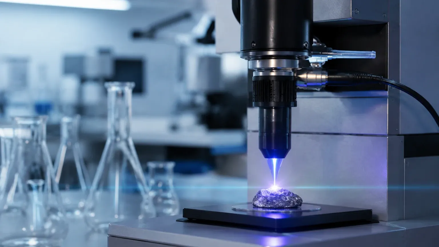
To effectively implement laser Raman spectroscopy instrumentation, one must first understand the underlying physics. The technique is based on the Raman effect, first discovered by C.V. Raman in 1928. When monochromatic light, typically from a laser, interacts with a sample, the photons are scattered. The vast majority of this scattering is elastic, meaning the scattered photons have the same energy (and wavelength) as the incident light; this is known as Rayleigh scattering.
However, a tiny fraction of the light—approximately one in every million photons—undergoes inelastic scattering. This is the Raman effect. In this process, the incident photon exchanges energy with the vibrational or rotational states of the molecules in the sample.
1. Stokes Scattering: If the molecule absorbs energy, the scattered photon has less energy and a longer wavelength than the incident light.
2. Anti-Stokes Scattering: If the molecule is already in an excited vibrational state and loses energy to the photon, the scattered photon has more energy and a shorter wavelength.
Because the energy shifts correspond directly to specific molecular bonds, the resulting spectrum acts as a unique "molecular fingerprint." This allows for the identification of chemical species, polymorphs, and even the measurement of stress or strain in crystalline materials.
Core Components of Laser Raman Spectroscopy Instrumentation
Industrial-grade Raman systems are comprised of several critical sub-systems designed to work in harmony under demanding conditions.
The Laser Source
The laser is the heart of the instrument. Its primary requirements are stability, narrow linewidth, and appropriate wavelength. Common wavelengths include:
* 532 nm (Green): Offers high scattering efficiency (scattering intensity is proportional to 1/λ⁴) but often triggers significant fluorescence in organic samples.
* 785 nm (Near-Infrared): The most common choice for industrial applications. It balances scattering efficiency with a reduced risk of fluorescence.
* 1064 nm (Infrared): Used for highly fluorescent or dark-colored samples, though it requires more sensitive (and expensive) detectors.
The Spectrometer and Grating
The spectrometer receives the scattered light and separates it into its constituent wavelengths using a diffraction grating. The resolution of the instrument depends on the groove density of the grating and the focal length of the spectrometer. In process environments, fixed-grating spectrometers are preferred over scanning systems due to their lack of moving parts and faster data acquisition.
The Detector
Most modern laser Raman spectroscopy instrumentation utilizes Charge-Coupled Device (CCD) detectors. For 785 nm systems, silicon-based CCDs are standard. For 1064 nm systems, Indium Gallium Arsenide (InGaAs) detectors are required. These sensors must often be thermoelectrically cooled to -60°C or lower to minimize dark noise and improve the signal-to-noise ratio.
Sampling Probes and Fiber Optics
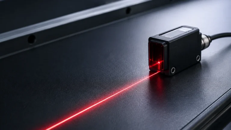
In B2B industrial settings, the instrument is often located in a control room or a climate-controlled enclosure, while the sampling probe is installed directly into the process line or reactor. Fiber optic cables, which can extend up to 100 meters (328 feet), transport the laser light to the sample and return the scattered signal to the spectrometer. Probes must be constructed from chemically resistant materials like Hastelloy or stainless steel, with sapphire windows to withstand high pressures and temperatures.
Selecting the Right Instrumentation for Process Monitoring
Choosing the correct Raman system requires a detailed analysis of the process environment and the target analytes. The following table provides a comparison of key selection factors based on typical industrial needs:
| Criteria | Laboratory Grade | Industrial/Process Grade | Portable/Handheld |
| :— | :— | :— | :— |
| Environment | Controlled, low vibration | High heat, vibration, dust | Field use, variable |
| Wavelength | Often multi-laser | Fixed (e.g., 785 nm) | Fixed (e.g., 1064 nm) |
| Enclosure | Open/Standard | IP65/NEMA 4X | Ruggedized/IP67 |
| Data Interface | Research software | OPC UA, Modbus, 4-20mA | Wireless/USB |
| Maintenance | High (alignment needed) | Low (factory aligned) | Minimal |
When integrating these systems, engineers must also consider the physical state of the sample. Raman is exceptionally effective for liquids and solids, but gas-phase Raman requires specialized high-pressure cells or long-pathlength capillaries due to the lower molecular density of gases.
Installation Considerations and Safety Protocols
Installing laser Raman spectroscopy instrumentation involves more than just mounting a probe. Because these systems utilize Class 3B or Class 4 lasers, safety is the paramount concern.
1. Laser Safety: Interlocks must be installed to ensure the laser deactivates if the fiber optic cable is disconnected or if the probe is removed from the process mount. Operators must be trained in laser safety standards (ANSI Z136.1).
2. Explosion Protection: In chemical plants or refineries, the probe and the area surrounding the process interface often fall under ATEX or Class I Div 1/2 classifications. Use of purge systems or intrinsically safe barriers for the electronic components is mandatory.
3. Probe Fouling: Just as a radar level meter requires a clear path to the surface, a Raman probe requires a clean sapphire window. In processes involving resins or slurries, automated cleaning sleeves or ultrasonic cleaners may be necessary to prevent signal attenuation.
4. Calibration and Validation: Industrial Raman systems require regular wavelength calibration (using standards like neon lamps or sulfur) and intensity calibration to ensure data consistency over months of continuous operation.
Synergizing Level Measurement and Chemical Analysis
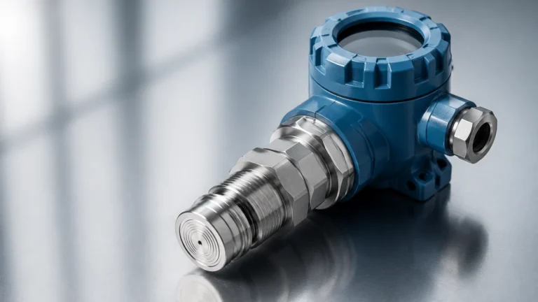
In a comprehensive industrial automation strategy, laser Raman spectroscopy instrumentation does not operate in isolation. It is part of a multi-parameter sensing network. For instance, in a batch reactor, a Welk radar level meter provides precise tracking of the liquid level to prevent overfills and manage inventory. Simultaneously, the Raman system monitors the conversion of reactants into products.
By combining the volumetric data from the Main Page level sensors with the compositional data from Raman spectroscopy, plant operators can calculate the total mass balance of specific chemical components in real-time. This synergy is particularly valuable in:
* Pharmaceutical Fermentation: Monitoring nutrient levels (Raman) while maintaining precise foam and liquid levels (Ultrasonic/Radar).
* Petrochemical Blending: Ensuring the correct octane rating (Raman) while managing tank farm inventory (Hydrostatic/Radar).
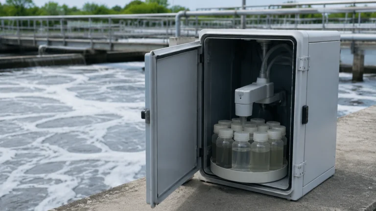
* Water Treatment: Detecting trace contaminants (Raman) while controlling flow and basin levels (Level Switches/Transmitters).
Limitations and Challenges
Despite its power, laser Raman spectroscopy instrumentation has specific limitations that must be managed:
* Fluorescence Interference: Some materials emit fluorescence that is orders of magnitude stronger than the Raman signal, effectively "swamping" the detector. Shifting to a longer wavelength laser (1064 nm) or using time-gated Raman can mitigate this.
* Dark Samples: Highly absorbent or black materials (like carbon black or coal) can absorb laser energy, leading to localized heating or even combustion of the sample. Lowering laser power or using a rotating sample stage is often required.
* Cost of Ownership: The initial capital expenditure for a high-quality Raman system is significant. However, the reduction in laboratory sampling costs and the improvement in process yield often result in a rapid Return on Investment (ROI).
Frequently Asked Questions (FAQ)
Q: How deep into a sample can a Raman probe measure?
A: Raman is primarily a surface or near-surface technique. In liquids, the measurement volume is typically within the first 1–5 mm from the probe window. In solids, penetration depends on the opacity of the material but is generally limited to a few hundred micrometers.
Q: Can Raman spectroscopy measure water-based solutions?
A: Yes. Unlike Infrared (IR) spectroscopy, where water is a strong absorber that masks other signals, water is a very weak Raman scatterer. This makes Raman an ideal tool for analyzing aqueous solutions and biological samples.
Q: How often does the laser need to be replaced?
A: Modern diode lasers used in industrial Raman instrumentation have long lifespans, typically ranging from 10,000 to 20,000 hours of continuous operation. Regular monitoring of laser power output can predict end-of-life before failure occurs.
Q: Is Raman spectroscopy suitable for hazardous environments?
A: Yes, provided the system is designed with fiber optic isolation. The sensitive electronics and the laser source can be housed in a safe zone, while only the passive fiber and the ruggedized probe head are located in the hazardous area.
Conclusion
Laser Raman spectroscopy instrumentation represents a significant leap forward in process monitoring. By providing molecular-level insights in real-time, it allows for a level of control that was previously impossible. When integrated with reliable physical measurement tools—such as the level measurement solutions provided by Welk—industrial facilities can achieve a holistic view of their operations, driving safety, quality, and profitability. For those looking to upgrade their monitoring capabilities, the combination of chemical analysis and precise level control is the gold standard of modern engineering.