Ultrasonic Gas Meter
Ultrasonic Gas Meter
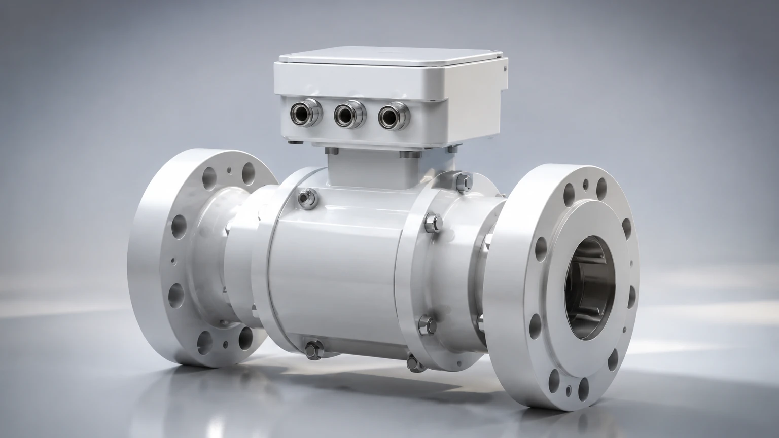
In the landscape of industrial process control and custody transfer, the ultrasonic gas meter has emerged as a primary technology for high-precision flow measurement. Unlike traditional mechanical meters that rely on moving parts, ultrasonic technology utilizes acoustic signals to determine the velocity of a gas stream. This transition toward digital, non-intrusive measurement is driven by the need for lower maintenance costs, higher turndown ratios, and improved long-term stability in sectors ranging from natural gas distribution to chemical processing.
Selecting the appropriate measurement technology requires a deep understanding of fluid dynamics and acoustic physics. For professionals managing complex industrial sites, reviewing various product options and application support on the Main Page can provide necessary insights into how these instruments integrate into broader automation frameworks.
The Principle of Transit-Time Ultrasonic Measurement
The fundamental operation of an industrial ultrasonic gas meter is based on the "transit-time" or "time-of-flight" principle. This method relies on the fact that the speed of an ultrasonic signal traveling in a moving gas is influenced by the velocity of that gas.
Acoustic Signal Propagation
In a typical configuration, two ultrasonic transducers are mounted on a pipe, acting as both transmitters and receivers. One transducer is located upstream and the other downstream, positioned at a specific angle relative to the gas flow.
1. Downstream Transmission: The upstream transducer emits a pulse that travels with the flow to the downstream receiver. The time taken is denoted as $t_{ab}$.
2. Upstream Transmission: The downstream transducer emits a pulse that travels against the flow to the upstream receiver. The time taken is denoted as $t_{ba}$.
Because the gas flow "carries" the sound wave in the downstream direction and "resists" it in the upstream direction, $t_{ab}$ will be shorter than $t_{ba}$.
Calculating Flow Velocity
The difference between these two transit times is directly proportional to the average velocity of the gas flow. The mathematical relationship can be simplified as:
$$V = \frac{L}{2 \cos \theta} \times \left( \frac{1}{t_{ab}} – \frac{1}{t_{ba}} \right)$$
Where:
* V is the average gas velocity.
* L is the distance between the transducers.
* θ is the angle of the acoustic path.
By multiplying the calculated velocity by the cross-sectional area of the pipe and applying corrections for pressure, temperature, and gas compressibility (Z-factor), the meter determines the actual and standard volume flow rates.
Multi-Path Configurations
For high-accuracy applications, such as fiscal billing or custody transfer, a single acoustic path is often insufficient because it only samples one section of the flow profile. Modern ultrasonic gas meters utilize multiple paths (ranging from 2 to 18 paths) to map the velocity profile across the entire pipe diameter. This compensates for turbulence and non-axial flow components, ensuring measurement uncertainty as low as ±0.1% to 0.5%.
Key Evaluation Criteria for B2B Procurement
When evaluating an ultrasonic gas meter for industrial use, several technical parameters must be verified to ensure the instrument meets the specific demands of the process environment.
1. Gas Composition and Speed of Sound
Ultrasonic meters are sensitive to the "Speed of Sound" (SoS) in the medium. The SoS varies significantly depending on the gas composition (e.g., methane content in natural gas, or the presence of heavier hydrocarbons). High-end meters perform internal SoS calculations and compare them to theoretical values based on gas chromatograph data to verify meter health.
2. Turndown Ratio
One of the greatest advantages of ultrasonic technology is its wide turndown ratio, often exceeding 100:1. Unlike orifice plates, which lose accuracy at low flow rates due to the square-root relationship of differential pressure, ultrasonic sensors can detect very low velocities (down to 0.1 m/s) while maintaining accuracy at high velocities (up to 30 m/s or higher).
3. Pressure and Temperature Limits
Standard industrial ultrasonic gas meters are designed to operate from atmospheric pressure up to 100 bar (1450 psi) or more. However, at very low pressures (below 1-2 bar), the acoustic coupling between the transducer and the gas becomes less efficient, potentially leading to signal loss. Temperature ratings typically span from -40°C to +150°C, though specialized high-temperature models exist for steam or hot process gases.
4. Diagnostic Capabilities
B2B buyers should prioritize meters with advanced onboard diagnostics. These systems monitor signal-to-noise ratios (SNR), gain levels, and path status. If a transducer begins to fail or if liquid contamination builds up on the sensor face, the meter can trigger an alert before the measurement fails entirely.
Comparative Analysis: Ultrasonic vs. Traditional Gas Meters
Choosing between ultrasonic and mechanical or differential pressure (DP) meters involves balancing initial capital expenditure (CAPEX) against long-term operational expenditure (OPEX).
| Feature | Ultrasonic Gas Meter | Turbine Meter | Orifice Plate (DP) |
| :— | :— | :— | :— |
| Moving Parts | None | Yes (Rotor/Bearings) | None |
| Pressure Drop | Negligible | Moderate | High |
| Maintenance | Low (Periodic cleaning) | High (Lubrication/Wear) | Medium (Edge inspection) |
| Turndown Ratio | High (>100:1) | Medium (20:1) | Low (4:1) |
| Accuracy | Very High (±0.5%) | High (±1.0%) | Moderate (±2.0%) |
| Initial Cost | High | Moderate | Low |
| Bi-directional | Yes | No | No |
While the initial cost of an ultrasonic gas meter is higher than an orifice plate or a turbine meter, the lack of pressure drop results in significant energy savings over time, especially in high-volume transmission lines. Furthermore, the absence of moving parts eliminates the risk of mechanical failure that could halt production.
Installation Guidelines and Best Practices
To achieve the specified accuracy, the ultrasonic gas meter must be installed according to strict engineering standards, such as AGA 9 or ISO 17089.
Straight Pipe Requirements
Ultrasonic meters are sensitive to flow profile disturbances caused by elbows, valves, and reducers. Generally, a minimum of 10 to 20 diameters (10D–20D) of straight pipe is required upstream of the meter, and 3 to 5 diameters (3D–5D) downstream. If space is limited, a flow conditioner (such as a perforated plate) must be used to normalize the flow profile.
Orientation and Mounting
* Horizontal Installation: This is the most common orientation. Transducers should be positioned in the 3 o'clock and 9 o'clock positions to prevent moisture or debris from settling on the transducer faces.
* Vertical Installation: Possible if the gas is dry. If liquids are present, vertical upward flow is preferred to prevent liquid accumulation at the meter base.
Acoustic Noise Mitigation
Pressure-regulating valves located near the meter can generate high-frequency ultrasonic noise that interferes with the meter’s signals. To mitigate this, the meter should be placed as far as possible from such valves, or acoustic silencers/heavy-walled piping should be employed.
Limitations, Risks, and Mitigation Strategies
Despite their versatility, ultrasonic gas meters are not universal solutions. Understanding their limitations is critical for process safety and reliability.
1. Signal Attenuation: Certain gases, such as high-concentration Carbon Dioxide (CO2) or very high-pressure Hydrogen, can absorb ultrasonic energy more readily than nitrogen or methane. This attenuation can lead to "signal blowout." In such cases, lower-frequency transducers are required.
2. Contamination: While ultrasonic meters can handle some particulates, heavy buildup of wax, oil, or scale on the transducer face will eventually block the signal. Regular inspection intervals should be established for "dirty" gas applications.
3. Minimum Pressure Requirements: As noted, these meters require a minimum gas density to transmit sound effectively. They are generally not suitable for deep vacuum applications.
4. Electronic Interference: In environments with heavy electromagnetic interference (EMI), shielded cabling and proper grounding are mandatory to prevent signal corruption between the meter body and the flow computer.
Frequently Asked Questions (FAQ)
Q: Can an ultrasonic gas meter measure steam?
A: Yes, specialized high-temperature ultrasonic meters are designed for saturated and superheated steam. However, the electronics must be isolated from the heat, and the transducers must be rated for the specific thermal cycles of steam systems.
Q: How often do the transducers need calibration?
A: Unlike mechanical meters, the "geometry" of an ultrasonic meter does not change over time. Many jurisdictions allow for "calibration by diagnostics," where the meter is only removed for flow lab recalibration every 5 to 10 years, provided the internal diagnostics show no drift.
Q: Is it possible to install ultrasonic sensors on existing pipes?
A: Yes, "clamp-on" ultrasonic gas meters exist for non-invasive measurement. While convenient, they generally offer lower accuracy (±2.0% to 5.0%) compared to inline (spool-piece) meters because the signal must pass through the pipe wall.
Q: What is the impact of gas temperature changes?
A: Since the speed of sound is temperature-dependent, the meter must have an integrated or external temperature sensor (RTD). The flow computer uses this data to correct the velocity calculation in real-time.
For engineers and project managers looking to integrate these instruments into a complete level and flow monitoring system, the Main Page serves as a technical resource for selecting compatible hardware and ensuring seamless site integration. By adhering to the principles of transit-time measurement and following rigorous installation protocols, industrial facilities can achieve unprecedented levels of accuracy and reliability in their gas measurement operations.