Polaris Vega
Polaris Vega
In the landscape of industrial automation, the demand for high-precision level measurement has led to the development of sophisticated radar technologies. The Polaris Vega platform represents a significant milestone in this evolution, particularly in the realm of 80 GHz radar sensors. For process engineers and plant managers, understanding the nuances of this technology is essential for optimizing inventory management, ensuring process safety, and reducing maintenance overhead. This guide explores the technical foundations of high-frequency radar measurement, the specific capabilities of the Polaris Vega architecture, and practical considerations for its implementation in diverse industrial environments.
Understanding Radar Level Measurement Principles
Before evaluating specific hardware like the Polaris Vega series, it is critical to understand the underlying physics of radar level sensing. Most modern high-performance radar sensors utilize the Frequency Modulated Continuous Wave (FMCW) principle, which differs significantly from older pulse-based systems.
The FMCW Principle
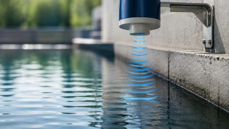
In an FMCW radar system, the sensor transmits a continuous signal with a constantly changing frequency (a frequency sweep or "chirp"). The signal travels to the surface of the medium, reflects, and returns to the sensor. Because the transmitted frequency is constantly changing, there is a measurable difference between the frequency being transmitted and the frequency being received at any given moment. This frequency difference ($Δf$) is directly proportional to the time of flight, and therefore the distance to the product surface.
Why 80 GHz Matters
The move from 26 GHz to 80 GHz (W-band) technology has revolutionized level measurement. The higher frequency results in a much shorter wavelength, which allows for several engineering advantages:
1. Narrower Beam Angle: An 80 GHz sensor can achieve a beam angle as narrow as 3° with a relatively small antenna. This allows the signal to bypass internal tank obstructions like agitators, heating coils, or ladders.
2. Higher Resolution: The wider bandwidth available at 80 GHz enables better signal separation, allowing the sensor to distinguish between the actual product surface and nearby interference or build-up on the antenna.
3. Smaller Dead Zones: High-frequency sensors typically have much smaller "blocking distances" (the area directly below the sensor where measurement is impossible), making them ideal for small vessels.
For those seeking a comprehensive range of these technologies, you can Review product options and application support to see how different radar frequencies align with specific industrial needs.
Key Features of the Polaris Vega Architecture
The Polaris Vega platform is designed to simplify the integration of radar sensors into complex industrial ecosystems. It focuses on several core pillars of performance: signal sensitivity, user interface consistency, and robust data processing.
Dynamic Range and Sensitivity
One of the standout features of this technology is its high dynamic range. In practical terms, this means the sensor can detect very weak reflections from media with low dielectric constants (εr), such as plastic powders or liquefied gases, while still handling strong reflections from metallic surfaces without saturating the receiver. This versatility makes it a "one-size-fits-all" solution for many facilities.
Signal Processing Algorithms
The Polaris Vega system employs advanced algorithms to filter out "noise." In many industrial tanks, turbulence, foam, or dust can create false echoes. The software architecture identifies the characteristic signature of the true level and ignores transient interference. This is particularly useful in solids applications where the surface angle (angle of repose) can vary significantly during filling and emptying cycles.
Comparison of Level Measurement Technologies
Selecting the right instrument requires a comparison of radar against other common technologies. The following table provides a general reference for selection based on typical performance metrics.
| Technology | Typical Accuracy | Max Range | Suitable Media | Key Advantage |
| :— | :— | :— | :— | :— |
| 80 GHz Radar (Polaris Vega) | ±1 mm | 120 m | Liquids & Solids | Narrow beam, non-contact |
| 26 GHz Radar | ±3 mm | 30 m | Primarily Liquids | Cost-effective for large tanks |
| Ultrasonic | ±0.25% of range | 15 m | Water/Wastewater | Economical, non-contact |
| Guided Wave Radar (GWR) | ±2 mm | 75 m | Liquids/Interface | Immune to foam/turbulence |
| Hydrostatic | ±0.1% FS | Varies | Clear Liquids | Simple, reliable for deep wells |
Selection Criteria for Industrial Applications
When specifying a sensor within the Polaris Vega framework, engineers must confirm several environmental and process variables to ensure long-term reliability.
1. Media Characteristics
The dielectric constant (εr) of the material is the most important factor. Materials with εr > 1.4 are generally easy to measure with non-contact radar. If the material has a lower dielectric constant, such as certain hydrocarbons or dry bulk solids, a sensor with higher sensitivity and specialized signal processing is required.
2. Process Conditions
* Temperature: Standard sensors typically handle up to 80°C, but high-temperature versions can withstand up to 450°C using cooling fins or ceramic seals.
* Pressure: Applications ranging from full vacuum to 160 bar (approx. 2320 psi) are common. The flange and seal material must be rated for these extremes.
* Chemical Compatibility: The wetted parts (usually PTFE, PEEK, or 316L Stainless Steel) must be resistant to the process media to prevent corrosion or leaching.
3. Vessel Geometry
Small, tall, and narrow tanks benefit most from the 80 GHz technology found in the Polaris Vega line. In these vessels, the narrow beam avoids the tank walls, preventing "ringing" or multiple reflection errors that plague lower-frequency sensors.

Installation and Engineering Best Practices
Correct installation is as important as selecting the right sensor. Even the most advanced Polaris Vega unit will fail if physical laws are ignored during mounting.
Positioning and Orientation
* Avoid the Center: Never mount a radar sensor in the exact center of a domed tank. This can cause the signal to focus and create false echoes from the tank roof.
* The 1/6th Rule: For cylindrical tanks, a common rule of thumb is to mount the sensor at approximately 1/6th of the tank diameter away from the wall. This balances the need to stay away from the wall while avoiding the center.
* Nozzle Length: Ensure the antenna extends slightly beyond the mounting nozzle. If the antenna is recessed deep within a narrow nozzle, the signal may reflect off the nozzle walls before even entering the tank.
Dealing with Obstructions
If an agitator is present, the sensor should be positioned so the beam does not strike the blades directly. Most Polaris Vega sensors allow for "False Signal Suppression," where the user can map the tank when empty. The sensor then remembers the location of static obstructions and subtracts them from the live measurement.
Limitations and Common Risks
While highly capable, radar technology is not a universal panacea. There are specific scenarios where performance may be degraded:
1. Heavy Foam: Dense, thick foam can absorb the radar signal entirely, preventing it from reaching the liquid surface. In such cases, Guided Wave Radar or hydrostatic transmitters may be more appropriate.
2. Extremely Low Dielectrics: If the material is nearly transparent to radar (like liquid nitrogen or very dry, fine powders), the signal may pass through the material and reflect off the tank bottom instead.
3. Condensation and Build-up: While 80 GHz radar handles some build-up well, heavy coating on the antenna lens can attenuate the signal. Integrated air purge connections are often recommended for dusty or condensing environments.
Maintenance and Troubleshooting
One of the primary benefits of the Polaris Vega platform is its low maintenance requirement. Since there are no moving parts and no contact with the media, wear and tear are minimal. However, periodic checks are advised:
* Visual Inspection: Check the antenna lens for heavy build-up or signs of chemical attack.
* Signal Strength Monitoring: Most modern sensors provide a "signal-to-noise" ratio. A significant drop in this ratio over time usually indicates either antenna fouling or a change in the process media characteristics.
* Firmware Updates: Ensure the Polaris Vega software is kept up to date to benefit from the latest signal processing improvements.
Frequently Asked Questions (FAQ)
Q: Can Polaris Vega sensors measure through plastic tank walls?
A: Yes, because plastic is transparent to radar, the sensor can often be mounted above a plastic tank to measure the level without any tank penetration, provided the plastic is not carbon-filled or metallic-lined.
Q: Is 80 GHz always better than 26 GHz?
A: Not necessarily. While 80 GHz is superior for narrow tanks and avoiding obstructions, 26 GHz can sometimes be more robust in the presence of heavy steam or very thick dust, as the longer wavelength is less affected by airborne particles.
Q: How do I calibrate the sensor?
A: Most sensors are calibrated by entering the "Zero" (empty) and "Span" (full) distances. Because the measurement is based on the speed of light, which is constant, the sensor does not require frequent re-calibration like pressure-based systems.
For more detailed technical specifications and to explore the full range of industrial level measurement solutions, please visit the Main Page to consult with application engineers.