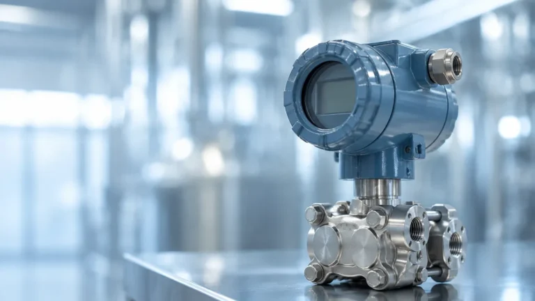
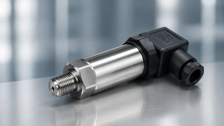
Fluid Differential Pressure Sensor
Fluid Differential Pressure Sensor
In the landscape of industrial process control, the fluid differential pressure sensor remains one of the most versatile and widely implemented technologies for level, flow, and pressure measurement. For engineering professionals managing water treatment, chemical processing, or oil and gas facilities, understanding the nuances of differential pressure (DP) is essential for ensuring system reliability and accuracy. This guide provides a technical deep dive into the principles, selection criteria, and installation requirements for fluid differential pressure sensors, serving as a practical reference for industrial applications.
1. Measurement Principles of Fluid Differential Pressure
Before selecting a sensor, it is critical to understand the underlying physics that allow a fluid differential pressure sensor to determine the level of a liquid within a vessel. The fundamental principle is based on hydrostatic pressure, which is the pressure exerted by a fluid at equilibrium at a given point within the fluid, due to the force of gravity.
The Hydrostatic Equation
For an open tank (vented to the atmosphere), the pressure at the bottom of the vessel is directly proportional to the height of the liquid column. The relationship is defined by the formula:
P = ρ × g × h
Where:
* P is the hydrostatic pressure (Pa or bar).
* ρ (rho) is the density of the fluid (kg/m³).
* g is the acceleration due to gravity (approximately 9.81 m/s²).
* h is the height of the liquid column (m).
Differential Pressure in Closed Vessels
In many industrial processes, fluids are stored in pressurized tanks. In these scenarios, the pressure at the bottom of the tank is the sum of the liquid's hydrostatic head and the gas pressure (blanket pressure) above the liquid. To measure only the liquid level, a fluid differential pressure sensor is used to subtract the head pressure (high-pressure side) from the gas pressure (low-pressure side).
* High-Pressure (HP) Side: Connected to the bottom of the tank to sense total pressure.
* Low-Pressure (LP) Side: Connected to the top of the tank to sense the gas/vapor pressure.
By calculating the difference (ΔP), the sensor isolates the pressure exerted solely by the liquid column, allowing for an accurate level reading regardless of fluctuations in the tank's internal pressure.
2. Key Components and Design Variations
A fluid differential pressure sensor is a sophisticated assembly designed to withstand harsh process conditions while maintaining high sensitivity. For a broad view of how these sensors integrate into wider industrial systems, engineers often refer to the Main Page of instrumentation catalogs to compare DP transmitters with alternative technologies like radar or ultrasonic sensors.
Sensing Elements
Most modern DP sensors utilize a metallic or ceramic diaphragm. When pressure is applied, the diaphragm deflects. This physical movement is converted into an electrical signal through various methods:
* Piezoresistive: Silicon-based strain gauges change resistance as the diaphragm moves.
* Capacitive: The diaphragm acts as a moving plate between two fixed capacitor plates; the change in capacitance is proportional to the pressure difference.
Remote Seals and Capillaries
In applications involving corrosive fluids, high temperatures, or hygienic requirements (such as food and beverage), the sensor may use remote diaphragms connected by oil-filled capillary tubes. This prevents the process fluid from coming into direct contact with the internal sensor electronics.
Manifolds
To facilitate maintenance and calibration without shutting down the process, DP sensors are typically mounted with a valve manifold (3-valve or 5-valve configurations). These allow the sensor to be isolated, vented, or equalized (bringing both sides to the same pressure to check the zero point).
3. Practical Selection Table: DP vs. Alternative Technologies
Choosing the right technology requires weighing the benefits of fluid differential pressure sensors against non-contact methods. The following table provides a comparison based on common industrial criteria.
| Feature | Fluid Differential Pressure (DP) | Radar (GWR/Non-Contact) | Ultrasonic Level Sensor |
| :— | :— | :— | :— |
| Measurement Type | Contact (Hydrostatic) | Non-Contact / Guided | Non-Contact (Sound) |
| Accuracy | High (0.04% to 0.1% span) | Very High (±1mm to 3mm) | Moderate (±0.25% range) |
| Effect of Foam | Minimal | Significant (Non-contact) | High Interference |
| Effect of Density | High (Requires constant ρ) | None | None |
| Temperature Limit | Up to 400°C (with seals) | Up to 450°C | Generally < 80°C |
| Installation | Requires tank penetrations | Top-mounted | Top-mounted |
| Best Use Case | Pressurized vessels, boilers | Chemical tanks, solids | Water/Wastewater basins |
4. Evaluation Criteria for Engineers
When specifying a fluid differential pressure sensor, several technical parameters must be confirmed to ensure long-term performance.
Turndown Ratio and Ranging
The turndown ratio defines the range over which a sensor can be calibrated without losing significant accuracy. For example, a sensor with a 100:1 turndown ratio can be adjusted to measure a very small fraction of its maximum range. This is vital for facilities that may change tank sizes or fluid types in the future.
Static Pressure Limits
It is a common mistake to focus only on the differential pressure range. Engineers must also verify the maximum static pressure the sensor body can withstand. In a high-pressure boiler, the ΔP might only be 500 mbar, but the static line pressure could exceed 100 bar.
Wetted Materials
The choice of diaphragm material is critical for chemical compatibility. Standard 316L stainless steel is common, but aggressive fluids may require:
* Hastelloy C-276: For high corrosion resistance.
* Tantalum: For strong acids.
* Monel: For hydrofluoric acid or seawater applications.
* Gold Plating: To prevent hydrogen permeation in high-temperature hydrogen service.
5. Installation and Maintenance Considerations
Correct installation is the single most important factor in the reliability of a fluid differential pressure sensor. Poorly designed impulse lines are the leading cause of measurement errors.
Impulse Piping Guidelines
1. Slope: Impulse lines should always be sloped (at least 1:12) to allow gas bubbles to escape back into the tank (in liquid service) or to allow condensate to drain (in gas service).
2. Length: Keep impulse lines as short as possible to reduce response lag and minimize the impact of ambient temperature changes.
3. Support: Ensure lines are properly supported to prevent vibration, which can introduce noise into the pressure signal.
Wet Leg vs. Dry Leg
In closed tanks where the vapor may condense, the LP (low-pressure) impulse line must be managed:
* Dry Leg: Used when the gas above the liquid will not condense at ambient temperatures. The line remains filled with gas.
* Wet Leg: Used when the vapor is likely to condense. The LP line is intentionally filled with a reference fluid (usually the process fluid or water) to a constant level. The weight of this liquid column must be accounted for during sensor calibration (Zero Elevation/Suppression).
6. Common Risks and Limitations
While highly reliable, fluid differential pressure sensors are not "set and forget" devices. Awareness of their limitations is key to avoiding process upsets.
Density Sensitivity
Because DP sensors measure mass (weight of the column), any change in fluid density will result in a level error. If a tank is calibrated for water at 20°C but is used for water at 80°C, the density drop will cause the sensor to report a lower level than actually exists. In applications with significant temperature swings, integrated temperature compensation or multi-variable transmitters are required.
Clogging and Sedimentation
In wastewater or slurries, the small-diameter impulse lines are prone to clogging. This can be mitigated by using diaphragm seals (flush-mounted) instead of traditional impulse piping, or by implementing periodic purging systems.
Ambient Temperature Effects
If the HP and LP impulse lines are at different temperatures (e.g., one side is in the sun and the other in the shade), the density of the fluid within the lines will differ, creating a "false" differential pressure. Insulating or heat-tracing the impulse lines is a standard solution in outdoor installations.
7. Frequently Asked Questions (FAQs)
Q: How often should a fluid differential pressure sensor be calibrated?
A: Most modern digital transmitters offer excellent long-term stability. A common industry standard is to perform a calibration check every 1 to 2 years, though critical safety loops may require more frequent verification.
Q: Can a DP sensor measure the level of solids?
A: Generally, no. DP sensors rely on the fluid properties of liquids to exert hydrostatic pressure equally. For solids like grain or plastic pellets, radar or ultrasonic technologies are preferred.
Q: What is the difference between a pressure transmitter and a differential pressure transmitter?
A: A standard pressure transmitter measures pressure relative to the atmosphere (gauge) or a vacuum (absolute) using a single port. A differential pressure transmitter has two ports and measures the difference between them.
Q: What happens if the LP and HP lines are swapped during installation?
A: The sensor will report a negative pressure or an error signal. Most smart transmitters allow the user to reverse the electronics via software, but it is best practice to physically correct the piping.
8. Conclusion and Pre-Purchase Checklist
The fluid differential pressure sensor remains a workhorse of industrial automation due to its proven track record and high accuracy in pressurized environments. However, successful implementation depends on rigorous application engineering.
Before proceeding with a project, technical teams should confirm the following:
1. Fluid Density: Is it constant, or does it vary with temperature/concentration?
2. Tank Geometry: Are there internal obstructions that might affect impulse line placement?
3. Vapor Phase: Will the gas above the liquid condense, requiring a wet leg or remote seal?
4. Cleaning Requirements: Does the process require CIP (Clean-In-Place) or SIP (Steam-In-Place) compatibility?
5. Safety Ratings: Does the installation area require ATEX, IECEx, or other explosion-proof certifications?
By addressing these factors and consulting detailed technical resources on the Main Page, engineers can ensure they select a measurement solution that provides accurate, repeatable data for years to come.