Level Tranmitter
Level Tranmitter
In the landscape of industrial process control, the ability to accurately monitor the volume or height of liquids and solids within a vessel is fundamental. A level tranmitter is an essential instrument that provides continuous feedback to control systems, ensuring safety, efficiency, and inventory accuracy. Unlike simple level switches that only indicate whether a substance has reached a specific point, a transmitter provides a linear output—typically 4-20mA, HART, or RS485—representing the exact level across a defined range.
Selecting the appropriate level tranmitter requires a deep understanding of the physical properties of the media, the environmental conditions of the vessel, and the specific measurement principles employed by different technologies. This guide explores the core technologies used in modern industrial level measurement, offering a technical framework for engineers and procurement professionals.
Core Measurement Principles
Before selecting a device, it is critical to understand how different sensors interact with the process media. Industrial level transmitters generally fall into two categories: contact and non-contact.
1. Radar Level Measurement (Non-Contact)
Radar technology has become the industry standard for challenging environments. It operates on the Time of Flight (ToF) principle. The transmitter emits high-frequency microwave pulses (typically in the 26GHz or 80GHz range) that travel at the speed of light. When these pulses hit the surface of the medium, they are reflected back to the sensor. The distance is calculated based on the time interval between transmission and reception.
* FMCW (Frequency Modulated Continuous Wave): Modern high-precision radar often uses FMCW. The transmitter emits a continuous signal with a constantly changing frequency. The difference in frequency between the emitted and received signal is proportional to the distance.
* Advantages: Unaffected by vacuum, high pressure, or temperature fluctuations. 80GHz models offer narrow beam angles, allowing for measurement in narrow tanks with internal obstructions.
2. Ultrasonic Level Measurement (Non-Contact)
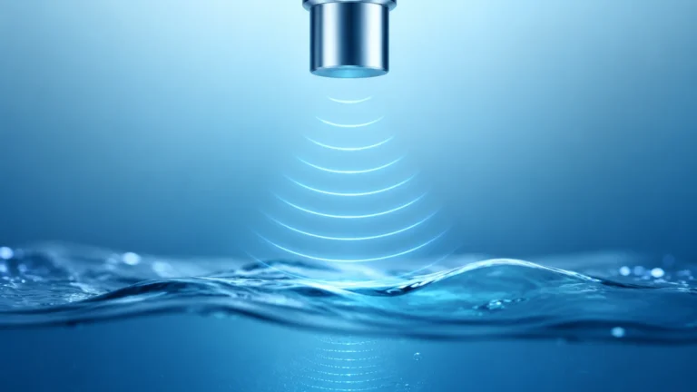
Ultrasonic transmitters function similarly to radar but use sound waves instead of electromagnetic waves. The transducer emits an ultrasonic pulse that reflects off the liquid surface.
* Principle: The distance is calculated using the formula: *Distance = (Speed of Sound × Time) / 2*.
* Limitations: Because sound requires a medium to travel, ultrasonic sensors cannot work in a vacuum. They are also sensitive to changes in air temperature (which affects the speed of sound), though most modern units include integrated temperature compensation.
3. Hydrostatic Level Measurement (Contact)
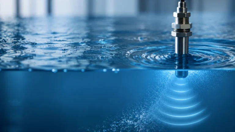
Hydrostatic transmitters measure the pressure exerted by a liquid column at a specific point. This is based on Pascal’s Law, where the pressure at the bottom of a tank is proportional to the height of the liquid and its specific gravity.
* Formula: *P = ρgh* (where P is pressure, ρ is density, g is gravity, and h is height).
* Application: These are often submersible sensors or flange-mounted pressure transmitters. They are highly reliable for vented tanks where the density of the liquid remains constant.
4. Magnetic Level Transmitters (Contact)
Magnetic level gauges are often paired with a transmitter for remote monitoring. A float containing a permanent magnet moves with the liquid level. Outside the chamber, a sensing rod containing a series of reed switches or a magnetostrictive wire detects the position of the float.
* Magnetostrictive Technology: This provides high-accuracy digital feedback by measuring the time it takes for a torsional wave to travel down a wire after being triggered by the float's magnetic field.
Technical Selection Criteria
Choosing a level tranmitter involves balancing performance requirements with cost and installation constraints. The following table provides a comparison of common technologies used in industrial automation.
| Technology | Accuracy | Range | Media Compatibility | Ideal Environment |
| :— | :— | :— | :— | :— |
| 80GHz Radar | ±1 mm | Up to 120m | Corrosives, solids, liquids | High-pressure, narrow tanks |
| Ultrasonic | ±0.25% | 0.5m – 15m | Water, wastewater, acids | Ambient pressure, open basins |
| Hydrostatic | ±0.1% – 0.5% | 1m – 200m | Clean liquids, oils | Deep wells, vented tanks |
| Magnetic | ±2 mm – 5 mm | 0.3m – 6m | Clean liquids, hydrocarbons | High-temperature, high-visibility |
Media Characteristics
When evaluating a level tranmitter, the first consideration must be the dielectric constant (εr) of the material if using radar. Materials with low dielectric constants, such as oils (εr < 2), reflect weaker signals than water-based liquids (εr ≈ 80). For very low dielectric materials, guided wave radar or hydrostatic sensors may be more appropriate.
Vessel Conditions
* Pressure and Temperature: Extreme temperatures can damage ultrasonic transducers. Radar and hydrostatic sensors are generally better suited for temperatures exceeding 80°C (176°F) or pressures above 3 bar (43.5 psi).
* Agitation and Foam: Surface turbulence can scatter ultrasonic and radar signals. In such cases, a stilling well or a guided wave radar (GWR) can provide a stable surface for measurement.
Installation Guidelines and Best Practices
Proper installation is as important as the technology itself. Even the most advanced transmitter will fail if positioned incorrectly.
1. Avoid the Dead Zone (Blocking Distance): Every non-contact sensor has a "dead zone" directly beneath the transducer where measurement is impossible. Ensure the maximum liquid level never enters this zone, typically 10cm to 50cm depending on the model.
2. Nozzle Geometry: For radar and ultrasonic sensors, the nozzle height and diameter must be considered. If the nozzle is too narrow or too long, the signal may reflect off the nozzle walls rather than the liquid surface.
3. Positioning: Sensors should be mounted away from the tank wall to avoid false reflections (interference). A common rule of thumb is to mount the sensor at 1/4 to 1/6 of the tank diameter from the wall.
4. Inflow Interference: Never install a transmitter directly above the filling inlet. The falling liquid or solids will interfere with the signal path, leading to erratic readings.
5. Submersible Cables: For hydrostatic sensors in deep wells, ensure the vent tube in the cable is not kinked or blocked. This tube allows the sensor to compensate for changes in atmospheric pressure.

Common Risks and Limitations
Engineers must be aware of potential failure points in level measurement systems:
* Vapor and Condensation: Heavy steam or condensation on an ultrasonic transducer face can attenuate the sound wave. Radar is largely unaffected by vapor, but heavy buildup on the antenna can still cause signal loss.
* Density Fluctuations: Hydrostatic transmitters rely on a constant liquid density. If the process involves mixing liquids of different densities or significant temperature-induced density changes, the level reading will drift unless compensated by a PLC.
* Build-up and Scaling: In wastewater or chemical processing, material can build up on the sensor. Non-contact radar with a PTFE (Teflon) face is often preferred here as it resists sticking and can be easily cleaned.
* Vacuum Conditions: Ultrasonic waves cannot propagate in a vacuum. In vacuum distillation or similar processes, radar or hydrostatic transmitters are mandatory.
Frequently Asked Questions (FAQ)
Q: Can I use an ultrasonic transmitter for measuring solids like grain or sand?
A: While possible, it is challenging. Solids do not create a flat reflective surface; they form cones and valleys that scatter sound. High-power radar with specialized algorithms for solids is generally more reliable.
Q: What is the difference between 2-wire and 4-wire transmitters?
A: A 2-wire transmitter uses the same pair of wires for both power and the 4-20mA signal, which is more cost-effective for installation. A 4-wire transmitter has separate power and signal lines, typically used when the device requires more power (e.g., heated displays or complex signal processing).
Q: How often should a level tranmitter be calibrated?
A: This depends on the industry. For inventory custody transfer, annual calibration is standard. For general process monitoring, a functional check every 12 to 24 months is usually sufficient, provided there is no significant drift.
Q: Does the color of the liquid affect the measurement?
A: No. Neither radar, ultrasonic, nor hydrostatic technologies are affected by the color or transparency of the liquid. This is a primary advantage over optical or laser-based sensors.
Conclusion
Selecting the right level measurement solution is a balance of physics and practical engineering. By understanding the principles of radar, ultrasonic, and hydrostatic measurement, facilities can ensure long-term reliability and minimize maintenance costs. For a comprehensive range of industrial instruments and technical support, professionals can refer to the Main Page to review product options and application support tailored to specific industrial needs. Whether dealing with corrosive chemicals, wastewater, or high-pressure steam, the correct transmitter configuration is the first step toward a safe and optimized process.