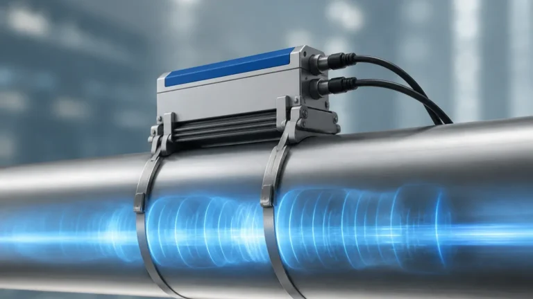
Magmeter History Function
Magmeter History Function
In the realm of industrial process control, the ability to track, record, and analyze flow data over time is critical for operational efficiency and regulatory compliance. The electromagnetic flowmeter, or magmeter, has evolved from a simple analog measurement device into a sophisticated diagnostic tool. Central to this evolution is the magmeter history function, a suite of data-logging and diagnostic capabilities that allow engineers to reconstruct process events, troubleshoot intermittent failures, and optimize maintenance schedules. Understanding both the historical development of these instruments and the technical functions of their modern data-logging systems is essential for any facility manager or instrumentation engineer.
Measurement Principles of Electromagnetic Flowmeters
Before evaluating the history function of a magmeter, it is necessary to understand the underlying physical principles that govern its operation. Magmeters operate based on Faraday’s Law of Electromagnetic Induction. This law states that a voltage is induced when a conductive fluid moves through a magnetic field.
Mathematically, the principle is expressed as:
E = B × L × v
Where:
* E is the induced voltage (signal).
* B is the magnetic field strength.
* L is the distance between the electrodes (typically the inner diameter of the pipe).
* v is the average velocity of the conductive fluid.
In a practical application, the magmeter consists of a non-conductive liner (such as PTFE or Hard Rubber) and a pair of electrodes. Electromagnetic coils located outside the flow tube generate a magnetic field. As the conductive liquid—such as water, slurry, or chemical acids—flows through the tube, it generates a voltage proportional to its velocity. The transmitter then converts this microvolt signal into a standard output, such as 4-20mA, pulse, or digital communication (HART, Modbus, or Profibus).
Because the measurement is independent of fluid density, viscosity, temperature, and pressure, magmeters are exceptionally versatile. However, the fluid must meet a minimum conductivity threshold, typically 5 μS/cm or higher, to ensure a reliable signal. For those seeking comprehensive instrumentation solutions, you can Review product options and application support on the Welk Main Page.
The Evolution and History of Magmeter Technology
The magmeter history function is the result of nearly two centuries of scientific advancement. The concept originated with Michael Faraday in 1832, who attempted to measure the flow of the River Thames by using the Earth's magnetic field and the conductivity of the water. While his experiment was hindered by the lack of sensitive instrumentation and the interference of electrochemical potentials, it laid the groundwork for future development.
It was not until the mid-20th century that the first commercial electromagnetic flowmeters appeared. Early models used AC (alternating current) excitation, which provided a continuous signal but suffered from significant zero-point drift and high power consumption. By the 1970s, the introduction of pulsed DC (direct current) excitation revolutionized the industry. This method allowed for a stable zero point by sampling the signal when the magnetic field was both on and off, effectively canceling out noise.
With the advent of microprocessors in the 1980s and 1990s, the "history function" moved from external paper chart recorders to internal digital memory. Modern magmeters now feature non-volatile memory capable of storing years of process data, error logs, and calibration history, providing a digital footprint of the entire pipe system's lifecycle.
Understanding the Magmeter History Function: Data Logging and Diagnostics
The modern magmeter history function serves three primary purposes: process auditing, diagnostic troubleshooting, and preventive maintenance.
1. Process Auditing and Data Logging
In industries such as water treatment and chemical processing, maintaining a record of totalized flow is a legal requirement. The history function records daily, weekly, and monthly totals. If a power failure occurs, the non-volatile memory ensures that the cumulative flow data is not lost. This allows operators to verify billing accuracy and resource consumption.
2. Event and Error Logging
When a process goes offline, engineers need to know why. The history function captures a timestamped log of alarms and events. Common logged events include:
* Empty Pipe Detection: Records when the sensor was not full, which can lead to measurement errors.
* Power Cycles: Tracks when the instrument was turned off or lost power.
* Excitation Alarms: Indicates issues with the magnetic coils.
* Configuration Changes: Logs when a user modifies parameters, providing an audit trail for security.
3. Advanced Diagnostics (Electrode Health)
One of the most valuable aspects of the history function is the ability to track electrode impedance. Over time, electrodes can become coated with scale or grease, or they may suffer from corrosion. By recording the baseline impedance at installation and tracking its change over months of operation, the magmeter can predict when cleaning or replacement is required before a total failure occurs.
Key Evaluation Criteria for Selecting Magmeters with Data History
When selecting a magmeter for a project, the history function should be evaluated alongside physical specifications. Use the following criteria to ensure the device meets your data requirements:
| Criteria | Requirement | Importance |
| :— | :— | :— |
| Memory Capacity | Minimum 10,000 data points | Ensures long-term storage without frequent downloads. |
| Sampling Rate | Adjustable (1s to 1hr) | Allows for high-resolution tracking during critical phases. |
| Export Formats | CSV, Excel, or PDF via USB/HART | Facilitates easy integration into reporting software. |
| Battery Backup | Real-time clock (RTC) backup | Ensures timestamps remain accurate during power outages. |
| Diagnostic Depth | Coil and electrode monitoring | Reduces the need for physical inspections in hazardous areas. |
Practical Selection Table: Liner and Electrode Materials
The reliability of the data recorded in the history function depends on the physical integrity of the sensor. Choosing the wrong materials can lead to signal noise that populates the history log with "ghost" errors.
| Material Type | Common Name | Application | Temperature Range |
| :— | :— | :— | :— |
| Liner: PTFE | Teflon | Corrosive chemicals, high temp | -20°C to +120°C |
| Liner: Hard Rubber | Ebonite | Water treatment, general use | 0°C to +60°C |
| Liner: Polyurethane| PU | Abrasive slurries, mining | -10°C to +50°C |
| Electrode: 316L SS | Stainless Steel | Water, mild chemicals | Standard |
| Electrode: Hastelloy| C276 | Strong acids and bases | High Corrosion |
| Electrode: Tantalum | Ta | High-concentration acids | Extreme Corrosion |

Installation Considerations for Optimal Data Accuracy
A magmeter’s history function is only as useful as the data it records. Poor installation leads to erratic readings and false alarms in the history log. To maintain data integrity, follow these engineering guidelines:
1. Straight Pipe Runs: To ensure a stable flow profile, install the meter with at least 5 diameters (5D) of straight pipe upstream and 2 diameters (2D) downstream from any valves, bends, or pumps.
2. Full Pipe Requirement: Magmeters must always be installed in a section of the pipe that remains 100% full. In horizontal lines, the electrodes should be positioned at the 3 o'clock and 9 o'clock positions to avoid air bubbles at the top and sediment at the bottom.
3. Grounding: This is the most critical step for magmeter accuracy. Because the induced voltage is in the microvolt range, any stray current in the piping can overwhelm the signal. Use grounding rings if the pipe is plastic or lined. Ensure the sensor and the fluid are at the same electrical potential.
4. Orientation: Vertical installation with upward flow is often preferred, as it naturally ensures a full pipe and prevents sediment buildup.
Limitations and Common Risks in Magmeter Data Recording
While the magmeter history function is a powerful tool, it has specific limitations that must be managed:
* Conductivity Limits: If the fluid conductivity drops below the threshold (e.g., deionized water), the signal will vanish. The history log will show a "low signal" or "empty pipe" error even if the pipe is full.
* Vacuum Conditions: Some liners, particularly PTFE, can collapse or peel away from the tube wall under vacuum conditions. This physical damage will permanently distort the flow data recorded in the history.
* Coating and Scaling: In wastewater applications, fats, oils, and greases (FOG) can coat the electrodes. This acts as an insulator, causing the flow reading to drop toward zero. Advanced history functions can detect this impedance change, but they cannot fix the physical coating; manual or electrolytic cleaning is required.
* Data Overwrite: Many internal logs operate on a "First-In, First-Out" (FIFO) basis. If the data is not exported periodically, older historical records will be overwritten by new data.
Frequently Asked Questions (FAQs)
Q: Can the magmeter history function be used for billing purposes?
A: Yes, provided the meter is calibrated and certified according to local weights and measures standards (such as OIML R49 or MID). The history function provides the necessary audit trail for billing disputes.
Q: How do I retrieve the history data from the instrument?
A: Most modern transmitters allow data retrieval via a local display menu, a plug-in USB drive, or remotely through communication protocols like HART or Modbus TCP/IP.
Q: Does the history function record flow direction?
A: Yes, most magmeters are bi-directional. The history log will typically record forward flow, reverse flow, and the net total separately.
Q: How long is the data stored if power is lost?
A: Modern instruments use EEPROM or Flash memory, which can retain the magmeter history function data for 10 years or more without power.
Conclusion
The integration of a robust history function into electromagnetic flowmeters represents a significant leap forward in process instrumentation. By combining the fundamental physics of Faraday’s Law with modern digital storage, these devices provide more than just a real-time flow rate; they offer a comprehensive narrative of the process environment. For engineers and operators, leveraging this data means fewer unplanned outages, more accurate billing, and a deeper understanding of hydraulic systems. When selecting your next flow measurement solution, prioritize instruments that offer transparent, easily accessible, and detailed historical logging to ensure long-term operational success.