Compressed Air Measurement
Compressed Air Measurement
Compressed air is frequently categorized as the "fourth utility" in industrial environments, alongside electricity, water, and natural gas. However, it is often the most expensive utility to produce, with up to 90% of the electrical energy consumed by a compressor being lost as heat. Effective compressed air measurement is therefore not merely a technical requirement but a financial necessity for modern manufacturing, chemical processing, and industrial automation.
In a professional B2B context, measuring compressed air involves tracking flow rates, pressure, and the levels of associated fluids like condensate and oil. This guide provides a technical overview of measurement principles, selection criteria, and installation best practices to help engineers and facility managers optimize their systems.
The Importance of Accurate Compressed Air Measurement
Without precise measurement, compressed air systems operate in a "blind" state. Industrial facilities often suffer from significant air leaks—sometimes losing 30% or more of their total generated capacity. By implementing a robust measurement strategy, organizations can achieve several critical objectives:
1. Leak Detection: Identifying discrepancies between compressor output and end-user consumption.
2. Cost Allocation: Accurately charging different departments or production lines for their specific air usage.
3. System Sizing: Determining if existing compressors are over-leveraged or if a facility has excess capacity that allows for expansion without additional capital expenditure.
4. Maintenance Scheduling: Monitoring pressure drops across filters and separators to signal when maintenance is required before a failure occurs.
Principles of Flow Measurement in Compressed Air Systems
When discussing compressed air measurement, flow is the primary metric. Because air is a compressible gas, measurement must account for changes in temperature and pressure. There are three primary technologies used for this purpose.
Thermal Mass Flow Measurement
Thermal mass flow meters are the industry standard for compressed air. The principle is based on heat transfer. The instrument typically features two sensors: one that is heated and one that measures the ambient temperature of the air. As air flows past the heated sensor, it carries away heat. The amount of energy required to maintain a specific temperature difference between the two sensors is directly proportional to the mass flow rate of the air.
* Advantages: Direct mass flow measurement (no need for separate pressure or temperature compensation), high sensitivity at low flow rates (excellent for leak detection), and no moving parts.
* Limitations: The air must be clean and dry. Moisture or oil droplets hitting the sensor can cause significant measurement errors.
Vortex Flow Measurement
Vortex meters operate on the Karman Vortex Street principle. An obstruction (bluff body) is placed in the flow stream, creating alternating vortices. The frequency of these vortices is proportional to the velocity of the fluid.
* Advantages: Highly durable and capable of handling high-velocity flows and higher temperatures.
* Limitations: Requires a minimum flow velocity to function (low-end sensitivity is poor) and requires separate pressure and temperature sensors to calculate mass flow.
Differential Pressure (DP) Measurement
DP flow meters use a primary element, such as an orifice plate or Pitot tube, to create a pressure drop. The square root of the pressure difference across the element is proportional to the flow rate.
* Advantages: Well-understood technology, suitable for very large pipe diameters.
* Limitations: High permanent pressure loss (which increases energy costs) and limited turndown ratio.
Level Measurement in Compressed Air Infrastructure
While flow measurement tracks the air itself, level measurement is critical for the peripheral components of a compressed air system. Compressed air naturally generates condensate (water and oil mixture) as it cools. This condensate must be managed to prevent corrosion in piping and damage to pneumatic tools.
Condensate Tank Monitoring
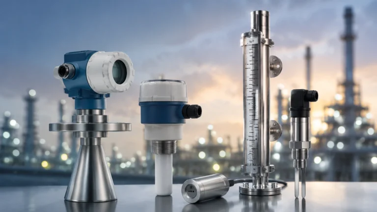
Air receivers and separator tanks collect moisture. Level sensors, such as hydrostatic transmitters or ultrasonic level sensors, are used to monitor the accumulation of this fluid. If the level becomes too high, it indicates a failure in the automatic drain valves, which can lead to water carryover into the main air lines.
Oil-Water Separators
In systems using oil-lubricated compressors, the condensate must be treated before disposal. Level switches and continuous level meters ensure that oil-water separators are functioning correctly and that the oil collection containers are not overflowing. For those seeking specific instrumentation for these applications, you can Review product options and application support on our Main Page to find compatible sensors for industrial tank monitoring.
Selection Criteria for Measurement Instrumentation
Choosing the right instrument for compressed air measurement requires an evaluation of the specific process conditions. Engineers should consider the following factors:
1. Turndown Ratio: This is the ratio of the maximum flow to the minimum flow the meter can accurately measure. For leak detection, a high turndown ratio (e.g., 100:1) is essential.
2. Accuracy and Repeatability: Standard industrial requirements usually call for ±1% to ±2% of the reading.
3. Pressure Drop: Every millibar of pressure drop caused by a flow meter requires the compressor to work harder, increasing energy costs. Thermal mass meters offer negligible pressure drop compared to orifice plates.
4. Gas Composition: Most meters are calibrated for air. If the gas mixture changes (e.g., nitrogen-enriched air), the meter must be recalibrated.
5. Installation Requirements: Consider the available straight pipe runs. Most meters require a specific distance of straight pipe upstream and downstream to ensure a stable flow profile.
Technology Comparison Table
| Feature | Thermal Mass Flow | Vortex Flow | Differential Pressure |
| :— | :— | :— | :— |
| Primary Measurement | Mass Flow | Volumetric Flow | Differential Pressure |
| Accuracy | ±1.0% to ±1.5% | ±1.0% | ±1.0% to ±2.5% |
| Turndown Ratio | Up to 100:1 | 15:1 | 4:1 |
| Pressure Loss | Very Low | Medium | High |
| Low Flow Sensitivity | Excellent | Poor | Poor |
| Maintenance | Low (if air is clean) | Low | Moderate (cleaning ports) |
Installation Best Practices
Proper installation is as important as the choice of technology. Even the most accurate compressed air measurement device will provide false data if installed incorrectly.
Straight Pipe Runs
To achieve a fully developed flow profile, flow meters typically require 10 to 20 diameters (D) of straight pipe upstream and 5D downstream. For example, if using a 50 mm pipe, you should have at least 500 mm to 1000 mm of straight pipe before the sensor. If there are bends, valves, or reducers closer than this, flow conditioners may be necessary.
Orientation and Moisture
In compressed air lines where moisture might be present, thermal mass meters should be installed horizontally or at a slight angle to prevent water from pooling on the sensor tips. If moisture is a persistent issue, the meter should be placed after the air dryer and filter set.
Calibration and Verification
Over time, sensors can "drift" due to contamination or electronic aging. Annual calibration is recommended for critical billing or energy management applications. Many modern digital meters offer self-diagnostic features that can verify the health of the sensor without removing it from the process line.
Common Risks and Limitations
When implementing compressed air measurement, be aware of the following challenges:
* Oil Carryover: In older reciprocating or oil-flooded screw compressors, oil mist can coat sensors. This acts as an insulator for thermal mass meters, leading to under-reading of flow.
* Vibration: Vortex meters are sensitive to pipe vibration. If the compressor room has high mechanical vibration, the meter may record "phantom" flow when the air is actually stagnant.
* Pulsating Flow: Reciprocating compressors create pulses in the air stream. These pulses can confuse many flow measurement technologies. Installing a large receiver tank between the compressor and the meter is the standard solution to dampen these pulses.
* Temperature Extremes: Ensure the instrument's electronics are rated for the ambient temperature of the compressor room, which can often exceed 40°C (104°F).
Frequently Asked Questions (FAQs)
Q: Should I measure flow at the compressor or at the point of use?
A: Ideally, both. Measuring at the compressor tells you the total production and efficiency (kWh/Nm³), while measuring at the point of use allows you to identify specific machines that are wasting air.
Q: How does pressure affect compressed air measurement?
A: If you are using a volumetric meter (like a vortex meter), the reading will change significantly as pressure changes. You must use the Ideal Gas Law to convert the volume to "Standard" or "Normal" cubic meters. Thermal mass meters handle this automatically.
Q: Can I use a water flow meter for compressed air?
A: No. The density and viscosity of air are vastly different from water. Using a meter designed for liquids will result in total failure or extreme inaccuracy.
Q: What is the difference between Nm³/h and Sm³/h?
A: Both refer to air volume at a reference pressure and temperature. Nm³ (Normal) typically uses 0°C and 1.013 bar, while Sm³ (Standard) often uses 15°C or 20°C. Always verify the reference conditions of your meter to ensure data consistency.
Conclusion
Effective compressed air measurement is the cornerstone of industrial energy management. By selecting the appropriate measurement technology—whether it be thermal mass flow for precise leak detection or robust level sensors for condensate management—facilities can significantly reduce operational costs and improve system reliability.
When planning an installation, always prioritize clean, dry air locations and adhere to straight-pipe requirements to ensure the longevity and accuracy of your instrumentation. For engineers looking to integrate these solutions into broader process control systems, visiting the Main Page provides access to a wide range of industrial level and flow measurement tools designed for the rigors of modern industry.