Flowmeters Gas
Flowmeters Gas
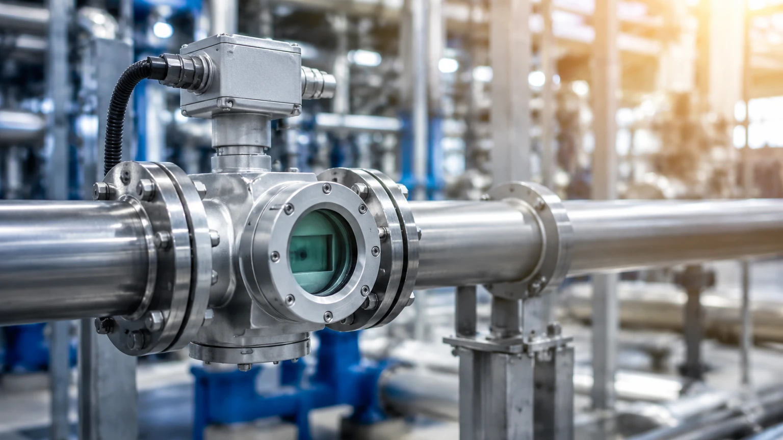
In industrial process control, the accurate measurement of gas flow is a critical requirement for safety, efficiency, and fiscal accounting. Unlike liquid measurement, gas is highly compressible, meaning its volume changes significantly with variations in temperature and pressure. Consequently, selecting the appropriate technology for flowmeters gas applications requires a deep understanding of fluid dynamics, gas properties, and the specific demands of the industrial environment.
Professional engineers and facility managers must evaluate several competing technologies, ranging from thermal mass and vortex shedding to ultrasonic and differential pressure. Each method offers distinct advantages and limitations depending on whether the application involves compressed air, natural gas, steam, or specialized industrial gases like nitrogen and argon. This guide provides a technical overview of gas flow measurement principles, selection criteria, and installation best practices to ensure reliable data in B2B industrial operations.
Measurement Principles for Gas Flow
To select the right instrument, one must first understand the physical principles that govern how different flowmeters gas devices interact with the medium. Industrial gas flow measurement is generally divided into two categories: volumetric flow and mass flow.
Thermal Mass Flow Measurement
Thermal mass flowmeters operate based on the principle of heat transfer. The sensor typically consists of two RTDs (Resistance Temperature Detectors); one serves as a reference, while the other is heated. As gas flows past the heated sensor, it carries away heat. The instrument measures the amount of energy required to maintain a constant temperature differential between the two sensors. Because heat transfer is directly related to the molecular mass of the gas, these meters provide a direct mass flow reading without requiring additional pressure or temperature compensation.
Vortex Shedding Principle
Vortex flowmeters utilize the Karman Vortex Street effect. When a gas flows past a non-streamlined "bluff body" placed in the flow stream, alternating vortices are shed on either side. The frequency of these vortices is directly proportional to the velocity of the gas. By measuring this frequency with a piezoelectric sensor, the meter determines the volumetric flow rate. This technology is highly valued for its lack of moving parts and its ability to handle high-temperature gases and saturated steam.
Ultrasonic Transit-Time Technology
Ultrasonic flowmeters for gas use acoustic transducers to send sound pulses across the pipe. The pulse traveling with the flow moves faster than the pulse traveling against it. The difference in transit time is proportional to the gas velocity. Modern multi-path ultrasonic meters provide high accuracy and are often used for custody transfer of natural gas. They offer the advantage of zero pressure drop and a wide turndown ratio.
Differential Pressure (DP)
DP flowmeters, such as orifice plates, Venturi tubes, and Pitot tubes, create a deliberate restriction in the flow path. According to Bernoulli’s equation, the pressure drop across this restriction is proportional to the square of the flow rate. While this is a mature and well-understood technology, it requires secondary transmitters for pressure and temperature to calculate compensated mass flow, and it introduces a permanent pressure loss into the system.
Key Selection Criteria for Industrial Gas Flowmeters
Choosing the correct flowmeter involves more than just matching a pipe size. Engineers must perform a comprehensive review of the process parameters to avoid premature equipment failure or inaccurate readings.
Gas Composition and Properties
The chemical makeup of the gas is the first consideration. Corrosive gases (such as wet chlorine or sour gas) require specialized materials like Hastelloy or Monel. Additionally, the density, viscosity, and specific heat of the gas must be known, especially for thermal mass meters, which are calibrated for specific gas mixtures.
Operating Pressure and Temperature
Gas density is a function of pressure and temperature. High-pressure applications (above 100 bar) may require specialized housing and flange ratings. Similarly, high-temperature applications (above 250°C) often rule out certain ultrasonic or thermal sensors, making vortex or DP meters more suitable.
Flow Range and Turndown Ratio
The turndown ratio is the ratio of the maximum flow to the minimum flow that the meter can accurately measure. For processes with high seasonal or operational variability—such as flare gas monitoring—a high turndown ratio (e.g., 100:1) is essential. Thermal mass meters excel in high-turndown scenarios, whereas vortex meters may have a "low-flow cutoff" where the velocity is insufficient to generate measurable vortices.
Technical Comparison Table
The following table summarizes the performance characteristics of common technologies used in flowmeters gas applications.
| Technology | Typical Accuracy | Turndown Ratio | Primary Advantages | Common Limitations |
| :— | :— | :— | :— | :— |
| Thermal Mass | ±1.0% of Reading | 100:1 | Direct mass flow; no P&T compensation needed. | Sensitive to moisture/droplets. |
| Vortex | ±1.0% of Rate | 20:1 | No moving parts; suitable for steam. | Minimum Reynolds number required. |
| Ultrasonic | ±0.5% to ±1.0% | 50:1 | Low pressure drop; high precision. | Higher initial capital cost. |
| Differential Pressure | ±1.0% to ±2.0% | 4:1 to 10:1 | Robust; industry-standard. | Permanent pressure loss; low turndown. |
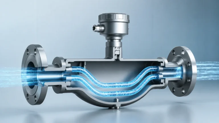
| Coriolis | ±0.5% of Rate | 100:1 | Extremely accurate mass flow. | Very expensive for large pipe sizes. |
Installation and Engineering Considerations
Even the most accurate flowmeter will provide erroneous data if installed incorrectly. Gas flow profiles must be fully developed and stable for the sensors to function as intended.
1. Straight Pipe Runs: Most gas flowmeters require a specific length of straight pipe upstream and downstream to eliminate turbulence caused by elbows, valves, or reducers. Typically, 10 to 20 diameters upstream and 5 diameters downstream are required. If space is limited, flow conditioners or internal honeycombs may be necessary.
2. Orientation: For gases that may contain moisture or condensables, the meter should be installed in a vertical pipe with upward flow, or on the top of a horizontal pipe, to prevent liquid buildup on the sensors.
3. Pressure and Temperature Taps: When using volumetric meters (like vortex or DP) that require compensation, the pressure and temperature sensors must be placed downstream of the flowmeter to avoid interfering with the flow profile.
4. Vibration and Noise: Ultrasonic and vortex meters can be sensitive to mechanical vibration or ultrasonic noise from nearby pressure-reducing valves. Isolation or specific mounting techniques may be required in these environments.
Challenges and Limitations in Gas Flow Monitoring
Understanding the limitations of flowmeters gas technology is essential for long-term reliability. One of the primary challenges is the presence of entrained liquids. In "wet gas" applications, liquid droplets can coat thermal sensors, leading to significant over-reading, or interfere with ultrasonic signals.
Another limitation is gas compressibility. Because gas volume changes with pressure, a meter measuring "Actual Cubic Meters per Hour" (ACMH) provides a different value than one measuring "Normal Cubic Meters per Hour" (Nm³/h). Standard or Normal units refer to the volume the gas would occupy at a reference pressure (usually 1.013 bar) and temperature (0°C or 15°C). Engineers must ensure that the flowmeter or the control system is correctly programmed to handle these conversions.
Finally, calibration remains a hurdle. Unlike liquid meters, which can be calibrated with water, gas meters should ideally be calibrated using the actual gas they will measure under operating pressures. Since this is not always feasible, many manufacturers use correlation fluids and atmospheric air, which may introduce small uncertainties when applied to high-pressure process gases.
Integrating Flow and Level Measurement for Process Automation
In many industrial settings, gas flow measurement does not exist in a vacuum. It is often part of a broader process control strategy that includes level measurement in storage tanks and separator vessels. For instance, in a nitrogen blanketing system, the flow of nitrogen gas into a tank must be coordinated with the liquid level inside that tank to maintain a constant pressure and prevent oxidative degradation of the product.
As a professional manufacturer of industrial measurement instruments, Welk provides the foundational level sensing technology—such as radar and ultrasonic level meters—that works in tandem with gas flow systems to ensure complete vessel management. For engineers looking to optimize their entire process loop, it is helpful to Review product options and application support on the Welk Main Page to understand how integrated level and flow data can improve plant safety and efficiency.
Frequently Asked Questions (FAQ)
Q: Can I use a liquid flowmeter for gas applications?
A: Generally, no. The physics of gas flow (compressibility, low density, high velocity) are significantly different from liquids. Using a meter designed for liquids on a gas line will result in extreme inaccuracies or failure to detect flow entirely.
Q: What is the difference between Nm³/h and Sm³/h?
A: Both are units of standardized volume. Nm³/h (Normal) usually refers to 0°C and 1.013 bar, while Sm³/h (Standard) often refers to 15°C or 20°C and 1.013 bar. It is critical to confirm the reference temperature used by your specific instrument or regional standard.
Q: How often should gas flowmeters be calibrated?
A: This depends on the criticality of the application and the gas type. For non-corrosive gases like compressed air, a 2-year interval is common. For custody transfer or highly corrosive gases, annual or even semi-annual calibration may be required to maintain regulatory compliance.
Q: Why is my thermal mass flowmeter reading high when the gas is wet?
A: Thermal mass meters measure heat dissipation. Because water has a much higher heat capacity than most gases, a liquid droplet hitting the heated sensor will cause a sudden, large cooling effect, which the meter interprets as a massive surge in gas flow.
Q: Do vortex flowmeters work at very low pressures?
A: Vortex meters require a minimum fluid density and velocity to create detectable vortices. At very low pressures (near atmospheric), the gas may be too "thin" to generate a signal, especially at low flow rates. In these cases, thermal mass or ultrasonic meters are usually preferred.