Turbidity Meter Inline
Turbidity Meter Inline
In industrial process control, the measurement of liquid clarity is a fundamental requirement for ensuring product quality, environmental compliance, and operational efficiency. A turbidity meter inline provides real-time, continuous monitoring of suspended solids within a process stream, allowing for immediate automated responses to changes in water or fluid quality. Unlike laboratory grab sampling, which provides a delayed snapshot of process conditions, inline systems offer a dynamic view of the process, which is essential for applications ranging from municipal water treatment to complex chemical manufacturing.
Turbidity is an optical property of a fluid that causes light to be scattered and absorbed rather than transmitted in straight lines through the sample. It is not a direct measurement of the mass of suspended solids, but rather an expression of the optical interference caused by those solids. Understanding the physics of light interaction, the engineering of the sensor interface, and the specific requirements of the installation environment is critical for selecting the correct turbidity meter inline for any given application.
Understanding Inline Turbidity Measurement Principles
To effectively implement a turbidity meter inline, one must first understand the primary optical methods used to quantify the presence of suspended particles. The choice of principle depends largely on the expected concentration of solids and the optical characteristics of the fluid.
Nephelometry (90° Light Scattering)
Nephelometry is the most common method for measuring low to medium turbidity levels. This technique involves directing a light beam into the fluid and measuring the amount of light scattered at a 90-degree angle to the incident beam. This method is highly sensitive to smaller particles and is the standard for monitoring drinking water quality. Standards such as ISO 7027 (using infrared light) and EPA 180.1 (using white light) define the specific parameters for these measurements. In an inline configuration, the sensor is typically housed in a flow cell that ensures a constant sample volume and minimizes stray light interference.
Light Absorption (Transmission)
For fluids with higher concentrations of suspended solids, where the liquid becomes opaque, the absorption or transmission method is used. This principle measures the attenuation of a light beam as it passes through a known path length of the fluid. The decrease in light intensity at the detector, located 180 degrees from the source, is proportional to the concentration of particles. This method is less sensitive at very low turbidity levels but is robust in heavy industrial effluents and sludge monitoring.
Backscatter Measurement
In extremely high-concentration applications, such as sludge density monitoring or concentrated chemical slurries, backscatter technology is employed. The sensor emits light and measures the portion reflected back at an angle greater than 90 degrees (often near 180 degrees). This technique is effective because it does not require the light to pass through the entire diameter of a pipe, which would be impossible in highly opaque fluids.
Core Components of a Turbidity Meter Inline System
A complete inline turbidity measurement system consists of several integrated components designed to withstand the rigors of a continuous process environment.
1. The Optical Sensor (Probe): The heart of the system, containing the light source (typically an LED or laser) and the photodetectors. Modern sensors often use infrared (IR) light sources to minimize the impact of fluid color on the measurement.
2. The Flow Cell or Immersion Assembly: This component interfaces the sensor with the process. A flow cell is a bypass assembly that diverts a small portion of the main process stream through a controlled chamber. Alternatively, immersion probes are inserted directly into tanks or large-diameter pipes.
3. The Transmitter/Controller: This unit processes the raw signal from the sensor, applies calibration curves, and provides a local display. It also handles the output signals, such as 4-20mA, Modbus, or HART, for integration into a PLC or SCADA system.
4. Cleaning Mechanisms: Because the optical windows of the sensor are prone to fouling (biofilm, scale, or grease), many inline systems include automated cleaning systems. These can be mechanical wipers, ultrasonic transducers, or high-pressure air/water jets.
Technical Selection Criteria for Industrial Applications
Selecting the appropriate turbidity meter inline requires a detailed analysis of the process fluid and the goals of the measurement. Engineers should evaluate the following criteria before procurement:
Measurement Range and Units
Turbidity is measured in several different units, the most common being NTU (Nephelometric Turbidity Units) and FNU (Formazin Nephelometric Units). While they are often used interchangeably, FNU specifically refers to measurements taken with an infrared light source according to ISO 7027. For high-concentration applications, units like FAU (Formazin Attenuation Units) or mg/L (if correlated to total suspended solids) may be used. The selected instrument must have a range that covers both normal operating conditions and potential process upsets.
Process Conditions: Temperature and Pressure
Industrial sensors must be rated for the specific temperature and pressure of the line. Standard sensors often operate up to 50°C and 6 bar (approx. 87 psi). However, for steam condensate monitoring or chemical reactors, high-temperature versions capable of withstanding up to 90°C or higher and higher pressure ratings are required. Ensuring the materials of construction (e.g., 316L stainless steel, PVC, or PTFE) are compatible with the process fluid is equally vital.
Influence of Bubbles and Color
Air bubbles in the process stream are a common source of error, as they scatter light similarly to solid particles, leading to artificially high readings. Systems used in aerated processes must include a bubble trap or be installed in a location where the pressure is high enough to keep gases in solution. Similarly, if the fluid has a strong inherent color, an infrared light source is preferred, as it is less affected by color absorption than white light.
Installation and Engineering Best Practices
The accuracy of a turbidity meter inline is heavily dependent on its physical installation. Poor placement can lead to noisy signals, frequent fouling, and inaccurate data.
Piping Configuration
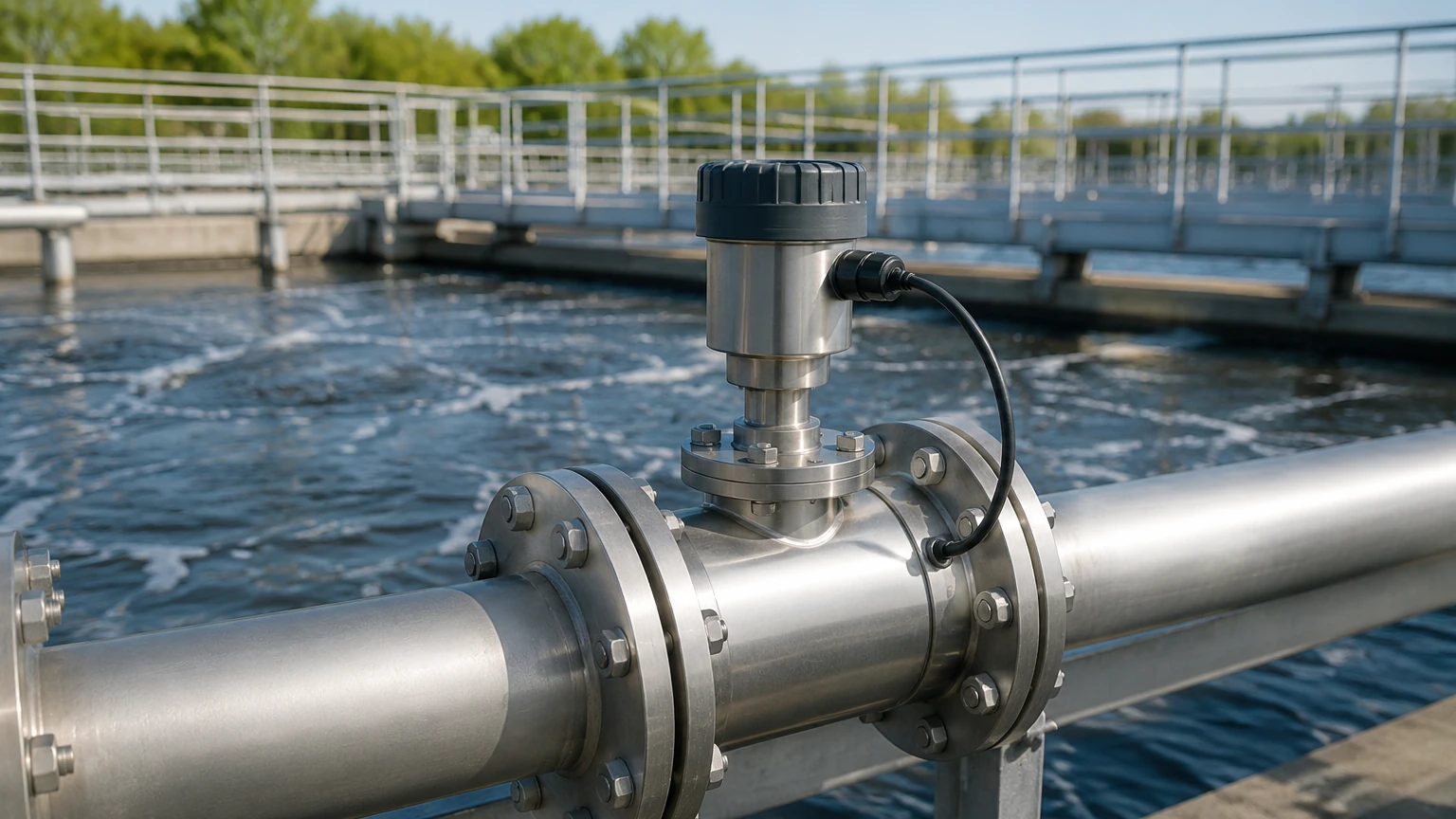
For pipe-mounted sensors, the probe should ideally be installed on a vertical section of pipe with the flow moving upwards. This ensures the pipe is always full and helps prevent the accumulation of air bubbles at the sensor head. If horizontal installation is necessary, the sensor should be placed at a 3-9 o'clock position; placing it at the top (12 o'clock) risks air interference, while the bottom (6 o'clock) risks sediment buildup.
Flow Rate Management
Most flow cells require a specific flow rate to maintain a representative sample and prevent solids from settling within the chamber. Typically, a flow rate between 0.5 and 2.0 liters per minute is recommended. If the main process line has highly variable flow, a pressure-regulated bypass line is often the best solution to maintain a stable environment for the sensor.
Upstream and Downstream Clearances
To avoid turbulence, which can introduce air bubbles or uneven particle distribution, the sensor should be installed away from pumps, valves, and sharp elbows. A general rule is to allow for at least 5 to 10 pipe diameters of straight run upstream and 2 to 3 diameters downstream of the measurement point.
Practical Selection Table
The following table provides a comparison of common inline turbidity technologies to assist in the initial selection process.
| Technology | Typical Range | Accuracy | Best Use Case | Limitations |
| :— | :— | :— | :— | :— |
| 90° Nephelometry | 0 – 1,000 NTU | High | Drinking water, filtered water, beverage clarity | Sensitive to bubbles; limited to low/mid solids |
| 180° Absorption | 10 – 10,000 FAU | Moderate | Wastewater effluent, industrial process water | Not suitable for very low turbidity (<10 NTU) |
| Backscatter | 1,000 – 100,000+ NTU | High (at high conc) | Sludge density, pulp and paper, chemical slurries | Expensive; requires specific calibration for particle type |
| Multi-Angle (Ratio) | 0 – 4,000 NTU | Very High | Variable processes, high-precision chemical | Complex electronics; higher initial cost |
Addressing Operational Limitations and Maintenance
While a turbidity meter inline is designed for continuous operation, it is not a "set and forget" instrument. Maintenance is the most significant factor in long-term reliability.
Fouling and Cleaning
Optical fouling is the primary cause of drift in turbidity measurements. In wastewater applications, biological growth can cover the lens within days. In chemical processes, scaling or oil films can be problematic. Selecting a sensor with an integrated wiper or an ultrasonic cleaning system significantly reduces manual intervention. For systems without integrated cleaning, a regular maintenance schedule (e.g., weekly or monthly) must be established to manually clean the optical windows with a soft cloth and appropriate solvent.
Calibration and Verification
Calibration should be performed using certified Formazin standards or manufacturer-supplied secondary standards. Because Formazin is toxic and has a limited shelf life, many operators prefer using stabilized Formazin or solid secondary standards for routine verification. It is important to note that inline sensors should be verified against laboratory measurements, but the laboratory results should not be used to "calibrate" the inline meter unless the sampling and timing are perfectly synchronized.
Integration with Other Measurements
In many industrial environments, turbidity is just one part of a broader analytical package. For instance, in water treatment, turbidity data is often used in conjunction with flow and level data to optimize chemical dosing. For engineers seeking comprehensive instrumentation solutions that integrate with level and flow management, visiting the Main Page provides access to technical specifications and product catalogs from Welk, ensuring that the selected turbidity meter inline works harmoniously with other process instruments.
Frequently Asked Questions (FAQs)
Q: How often should an inline turbidity meter be calibrated?
A: This depends heavily on the application. In clean water applications, a quarterly calibration may suffice, with monthly verifications. In high-fouling environments, monthly calibration may be necessary. Always follow the manufacturer's recommendations and use certified standards.
Q: Can I use an inline turbidity meter to measure Total Suspended Solids (TSS)?
A: Yes, but only through correlation. Turbidity and TSS are related but not identical. You must take multiple grab samples, measure them for TSS in a lab, and compare them to the turbidity readings at that exact time to create a site-specific correlation curve.
Q: What is the difference between NTU and FNU?
A: NTU (Nephelometric Turbidity Units) is generally used when referring to measurements made with a white light source (EPA 180.1). FNU (Formazin Nephelometric Units) refers to measurements made with an infrared light source (ISO 7027). Infrared is often preferred in industrial settings because it is less affected by the color of the liquid.
Q: How do I prevent air bubbles from affecting the reading?
A: Ensure the sensor is installed in a pressurized line, use a vertical pipe with upward flow, or install a bubble trap in a bypass line. In some cases, increasing the backpressure on the flow cell can help keep gas in solution.
Q: Does the pipe material affect the measurement?
A: In a direct pipe insertion, the internal reflection from the pipe walls can interfere with the sensor, especially in small-diameter pipes. Using a matte-finish internal coating or a dedicated flow cell designed by the manufacturer can mitigate this issue.
By carefully considering the measurement principle, installation environment, and maintenance requirements, engineers can successfully implement a turbidity meter inline to provide stable, accurate, and actionable data for process optimization.