Weld in Thermowell
Weld in Thermowell
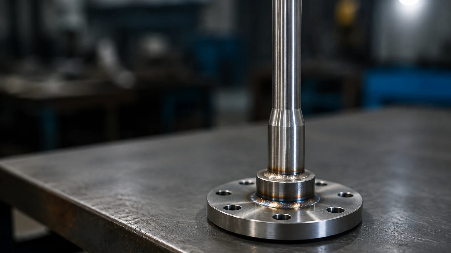
In the landscape of industrial process control, the integrity of a measurement point is as critical as the accuracy of the sensor itself. A weld in thermowell represents one of the most robust methods for integrating temperature sensors into high-pressure, high-temperature, or high-velocity systems. Unlike threaded or flanged alternatives, a welded connection provides a permanent, leak-proof seal that is essential in critical applications where process fluid containment is paramount. This guide examines the engineering principles, selection criteria, and installation requirements for weld in thermowells within the context of modern industrial automation.
Measurement Principles and the Role of the Thermowell
A thermowell is essentially a pressure-tight receptacle designed to accept a temperature sensing element, such as a Resistance Temperature Detector (RTD) or a thermocouple. Its primary function is to act as a barrier between the process media and the sensitive instrument.
Heat Transfer Dynamics
The measurement principle relies on thermal conduction. As the process fluid flows around the thermowell, heat is transferred from the fluid to the thermowell wall, and subsequently to the air gap (or thermal paste) and the sensor inside. Because the thermowell adds mass and a physical barrier, it introduces a "thermal lag" or response time delay. Engineers must balance the thickness of the thermowell wall—required for structural integrity—against the need for rapid response times in dynamic processes.
Protection and Maintenance
Beyond isolation, the thermowell protects the sensor from corrosion, high pressures, and physical damage caused by fluid velocity (impingement). Crucially, it allows for the removal and calibration of the temperature sensor without breaching the process boundary. In systems where downtime is costly, the ability to swap a sensor while the tank or pipe remains pressurized is a significant operational advantage.
The Advantages of Weld in Thermowells
While threaded and flanged thermowells are common, the weld in thermowell is preferred in specific high-stakes environments. The choice of a welded connection is usually driven by the following factors:
1. Zero Leakage Risk: In applications involving hazardous, toxic, or extremely high-pressure fluids, even the slight risk of a failed gasket (flanged) or a stripped thread (threaded) is unacceptable. A full-penetration weld ensures the thermowell becomes an integral part of the piping or vessel wall.
2. High Pressure and Temperature Ratings: Welded connections are not limited by the pressure ratings of flanges or the mechanical limits of NPT threads. They are often the only viable choice for supercritical steam lines or high-pressure chemical reactors.
3. Vibration Resistance: In high-velocity flow streams, threaded connections can loosen over time due to mechanical vibration. A welded joint provides superior structural damping and fatigue resistance.
4. Compact Profile: Weld-in designs often require less space than flanged assemblies, making them ideal for tight piping manifolds where multiple instruments are clustered together.
For engineers designing integrated systems that include level, pressure, and temperature monitoring, selecting the right mounting style is critical. To explore how these components fit into a broader instrumentation strategy, you can visit the Main Page to review product options and application support.
Key Design and Selection Criteria
Selecting a weld in thermowell requires a deep understanding of the process conditions. The following parameters are the most critical in the specification process.
Material Compatibility
The material of the thermowell must be compatible with both the process fluid and the piping material to ensure weld integrity. Common materials include:
* 316/316L Stainless Steel: The standard for most water treatment and general chemical applications.
* Hastelloy C-276: Reserved for highly corrosive environments involving chlorides or strong acids.
* Inconel 600: Used for high-temperature oxidation resistance.
* Chrome-Moly Steels (e.g., F11, F22): Standard for high-temperature steam service in power generation.
Shank Configuration
The "shank" is the portion of the thermowell that extends into the process. There are three primary designs:
* Straight Shank: The diameter is constant along the entire insertion length. It is simple to manufacture but most susceptible to vibration.
* Tapered Shank: The diameter decreases towards the tip. This design provides a higher strength-to-weight ratio and a higher natural frequency, making it suitable for high-velocity flows.
* Stepped Shank: The diameter is reduced abruptly near the tip. This minimizes the thermal mass around the sensor, significantly improving response time while maintaining a thick base for strength.
Insertion Length (U-Length)
The insertion length must be sufficient to ensure the sensing element is fully immersed in the process stream to avoid "stem conduction error," where heat escapes through the thermowell wall to the outside environment, leading to a lower-than-actual temperature reading. A general rule of thumb is an insertion length of at least 10 times the thermowell tip diameter for liquids and 15 times for gases.
Installation Best Practices for Welded Connections
The installation of a weld in thermowell is a permanent procedure that requires qualified welding personnel and specific techniques to ensure safety and longevity.
1. Weld Preparation
The pipe or vessel wall must be prepared with a socket or a beveled hole depending on the thermowell design. A "socket weld" thermowell fits into a recessed hole and is joined with a fillet weld, while a "butt weld" or "full penetration" design requires a beveled edge on both the thermowell and the pipe to allow for a deep, structural weld.
2. Orientation and Flow
In piping, the thermowell should ideally be installed against the flow (angled at 45 degrees) or in an elbow. This increases the surface area exposed to the fluid and helps mitigate the effects of wake frequency vibration. If installed perpendicular to the flow, the wake frequency calculations become even more critical.
3. Welding Metallurgy
Post-weld heat treatment (PWHT) may be required for certain alloy steels to relieve internal stresses and prevent hydrogen embrittlement. Furthermore, the weld filler metal must be carefully matched to the base metals to prevent galvanic corrosion or cracking.
Performance Limitations and Risk Mitigation
Despite their robustness, weld in thermowells are subject to physical laws that can lead to failure if not properly accounted for.
Wake Frequency and Resonance
As fluid flows past a cylindrical thermowell, it creates vortices (Von Kármán vortex street). If the frequency of these vortices matches the natural frequency of the thermowell, resonance occurs. This can lead to rapid fatigue failure and the thermowell snapping off into the process stream. Engineers must perform a wake frequency calculation according to ASME PTC 19.3 TW to ensure the design is safe for the specific fluid velocity and density.
Corrosion and Erosion
In abrasive slurries or high-velocity steam, the leading edge of the thermowell can erode over time. While a weld in thermowell is permanent, it is still a wear item. In such cases, specialized coatings like Stellite or Tungsten Carbide may be applied to the shank to extend its service life.
Integration with Level Measurement Systems
In many industrial tanks, temperature and level measurement are inextricably linked. For instance, hydrostatic level transmitters rely on the density of the liquid to calculate the level. Since density changes with temperature, a weld in thermowell is often installed at the bottom of the tank to provide real-time temperature compensation for the level reading.
Similarly, in high-pressure boilers, both the level of the water and the temperature of the steam must be monitored with high-integrity welded instruments to meet safety codes. Manufacturers like Welk provide a range of instrumentation that works in tandem with these robust mounting solutions to ensure comprehensive process visibility.
Practical Selection Table
| Feature | Straight Shank | Tapered Shank | Stepped Shank |
| :— | :— | :— | :— |
| Flow Velocity | Low (< 5 m/s) | High (> 15 m/s) | Medium (5-15 m/s) |
| Response Time | Slow | Moderate | Fast |
| Structural Strength | Moderate | Highest | High at base, Low at tip |
| Cost | Lowest | Highest | Moderate |
| Common Application | Large tanks, low flow | High-pressure steam | Chemical reactors |
Frequently Asked Questions (FAQ)
Q: Can a weld in thermowell be replaced?
A: Yes, but it is a significant undertaking. The old thermowell must be ground out or cut from the vessel, the surface must be re-prepped, and a new unit must be welded in. This is why material selection and wake frequency calculations are so critical during the design phase.
Q: What is the difference between a socket weld and a butt weld thermowell?
A: A socket weld thermowell slides into a pre-machined socket in the pipe wall or a "weldolet" and is welded around the circumference. A butt weld thermowell is placed end-to-end against a pipe or nozzle and welded through the entire thickness of the metal. Butt welds are generally stronger and easier to inspect via X-ray (radiography).
Q: How do I choose between a flanged and a weld in thermowell?
A: Choose flanged if you need to remove the thermowell for cleaning or inspection every few years. Choose weld-in if the process is extremely high pressure, involves hazardous chemicals where leaks are unacceptable, or if the system is subject to high vibration.
Q: Does the welding process affect the sensor?
A: The sensor should never be inside the thermowell during the welding process. The extreme heat from the welding torch can destroy the RTD or thermocouple elements. Only insert the sensor after the weld has cooled and been inspected.
Conclusion and Next Steps
The weld in thermowell is a cornerstone of high-integrity process instrumentation. By providing a permanent, leak-proof barrier, it ensures that temperature measurement remains accurate and safe even in the most demanding industrial environments. However, the permanence of the installation means that there is little room for error in the design phase.
Before proceeding with a project, engineers should confirm the process fluid velocity, pressure, and chemical composition. Performing an ASME PTC 19.3 TW calculation is a non-negotiable step for any pressurized flow application. For those seeking reliable measurement solutions across water treatment, chemical, or oil and gas sectors, reviewing the latest technology options on the Main Page can provide the necessary technical foundation for a successful installation.