Coreolis Flow Meter
Coreolis Flow Meter
In the landscape of industrial process control, the coreolis flow meter stands as one of the most versatile and accurate instruments available for measuring fluid dynamics. Unlike traditional volumetric flow meters that calculate flow based on velocity or space occupied, a coreolis flow meter measures mass flow directly. This distinction is critical in industries where chemical reactions, custody transfer, and precise blending require an understanding of the actual quantity of matter moving through a pipe, rather than just its volume, which can fluctuate with temperature and pressure.
While many facilities focus heavily on tank inventory via level measurement, integrating high-precision flow data allows for a dual-verification system. For engineers seeking comprehensive instrumentation strategies, visiting the Main Page of a professional manufacturer provides a broader perspective on how flow and level data work in tandem to optimize industrial automation.
The Measurement Principle: The Coriolis Effect
To understand how a coreolis flow meter functions, one must look at the physics of the Coriolis force. This force is an inertial force that acts on objects in motion within a frame of reference that rotates. In the context of a flow meter, this rotation is simulated through high-frequency vibration.
Oscillating Tubes
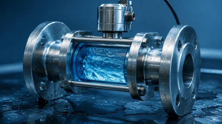
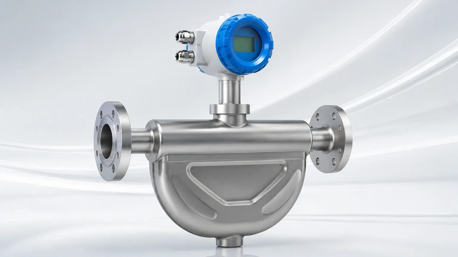
Inside the meter, the fluid passes through one or two measuring tubes. These tubes are induced to vibrate at their resonant frequency by an electromagnetic drive coil. When there is no flow, the tubes vibrate in a uniform, symmetrical manner. Both the inlet and outlet sides of the tube reach the peak of their oscillation cycle at the exact same time.
Phase Shift and Mass Flow
As fluid begins to flow through the vibrating tubes, the Coriolis effect takes hold. The fluid moving toward the center of the oscillation resists the upward motion of the tube, pushing down against it. Conversely, fluid moving away from the center resists the downward motion, pushing up. This creates a twisting effect or a "phase shift" between the inlet and outlet sections of the tube.
Sensors located at the inlet and outlet (pick-off coils) measure this time delay ($Δt$). This phase shift is directly proportional to the mass flow rate. Because the measurement relies on inertia and mass rather than fluid velocity or volume, it is inherently immune to changes in viscosity, density, and flow profile (laminar or turbulent).
Density and Temperature Measurement
Beyond mass flow, the coreolis flow meter is a multivariable instrument.
1. Density: The resonant frequency at which the tubes vibrate depends on the total mass of the tubes and the fluid inside them. By measuring this frequency, the meter can calculate the fluid's density in real-time.
2. Temperature: Since the elasticity of the metal tubes changes with temperature, an internal RTD (Resistance Temperature Detector) monitors the tube temperature to compensate the flow and density calculations. This temperature data is also available as a secondary process output.
Why Use a Coreolis Flow Meter Over Other Technologies?
The primary advantage of the coreolis flow meter is its extreme accuracy, often reaching ±0.1% or even ±0.05% of the flow rate. This makes it the preferred choice for high-value fluids and critical process applications.
Comparison with Volumetric Meters
Volumetric meters, such as turbine or ultrasonic meters, require compensation for temperature and pressure to derive mass. In contrast, the mass measured by a Coriolis meter remains constant regardless of whether the fluid expands or contracts. This eliminates the need for external flow computers and additional sensors in many applications.
Relationship to Level Measurement
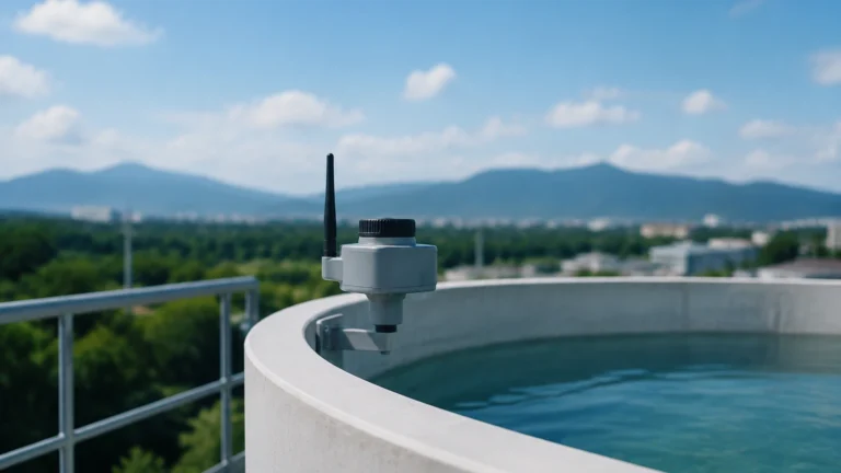
In process engineering, flow and level are two sides of the same coin. A level meter provides the "static" inventory in a tank, while a coreolis flow meter provides the "dynamic" data of what is entering or leaving that tank. By comparing the mass flow integrated over time against the change in level (converted to mass via density), operators can detect leaks, verify pump performance, and ensure mass balance across a plant. For those integrating these systems, reviewing advanced radar or ultrasonic level sensors alongside flow solutions is a standard practice for comprehensive process transparency.
Practical Selection Criteria
Selecting the right coreolis flow meter requires an analysis of the fluid properties and the physical constraints of the installation site. Use the following criteria to evaluate your requirements:
1. Mass Flow Range
Identify the minimum and maximum flow rates. Coriolis meters have excellent turndown ratios (often 100:1), but accuracy typically degrades at the very bottom end of the range. Ensure the "zero stability" of the meter is sufficient for your lowest expected flow.
2. Material Compatibility
The wetted parts must be compatible with the process fluid. Common materials include:
* 316L Stainless Steel: Standard for water, food, and mild chemicals.
* Hastelloy C22/C276: For highly corrosive acids and chlorides.
* Titanium: Used for specific chemical applications or where weight is a concern.
3. Pressure Drop
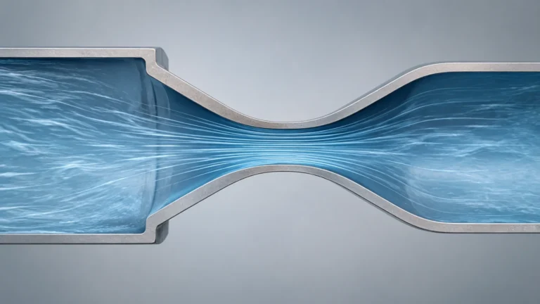
Because the fluid must be diverted through the measuring tubes (which are often smaller than the process piping), a pressure drop occurs. High-viscosity fluids will experience a more significant pressure drop. Engineers must ensure that the available system pressure can overcome this resistance without causing cavitation or flashing.
4. Tube Geometry
* U-Shaped Tubes: Offer high sensitivity and are generally better for low-flow applications. However, they can be bulky and may trap air or sediment if not oriented correctly.
* Straight Tubes: Easier to clean (CIP/SIP), have a lower pressure drop, and are more compact. They require more sophisticated electronics to measure the smaller phase shifts associated with straight-tube oscillation.
Selection Table for Common Applications
| Application Type | Recommended Tube Shape | Material | Typical Accuracy | Key Consideration |
| :— | :— | :— | :— | :— |
| Chemical Dosing | U-Shape (Small Bore) | Hastelloy | ±0.10% | Chemical compatibility |
| Food & Beverage | Straight Tube | 316L (Polished) | ±0.15% | Hygienic cleaning (CIP) |
| Oil & Gas Transfer | U-Shape (Large Bore) | Carbon Steel / 316L | ±0.05% | High-pressure ratings |
| Gas Measurement | U-Shape | 316L | ±0.50% | High velocity/low density |
| Slurries | Straight Tube | Wear-resistant alloy | ±0.20% | Erosion and clogging |
Installation Considerations and Best Practices
To maintain the high accuracy of a coreolis flow meter, proper installation is paramount. The meter is sensitive to external vibrations and mechanical stress, which can interfere with the tube's natural oscillation.
Orientation
* Liquids: The meter should ideally be installed in a vertical pipe with upward flow. This ensures the tubes remain full and prevents air bubbles from being trapped. If installed horizontally, the tubes should point downward (flag position) to avoid sediment buildup.
* Gases: For gas applications, the tubes should point upward in a horizontal installation to allow any condensed liquids to drain out.
Support and Vibration
The meter must be securely supported. It is a common misconception that the meter should be "floated" or isolated with flexible couplings; in reality, the piping on either side of the meter should be rigidly anchored to prevent external pipe vibrations from reaching the sensor tubes. However, the meter should not be used to support the weight of the piping.
Entrained Air (Two-Phase Flow)
One of the biggest challenges for a coreolis flow meter is entrained air in a liquid stream. Air bubbles dampen the tube vibration, leading to "stalling" or significant measurement errors. If air is expected, an air eliminator should be installed upstream, or the meter should be configured with advanced digital signal processing (DSP) designed to handle two-phase flow.
Limitations and Risks
While highly capable, the coreolis flow meter is not a universal solution for every scenario:
* Initial Cost: They are significantly more expensive than electromagnetic or vortex meters. The ROI must be justified by the need for mass flow accuracy or density data.
* Size and Weight: Large-diameter Coriolis meters (above 200 mm / 8 inches) are extremely heavy and require substantial structural support.
* Gas Density: Because gases have very low mass, the Coriolis force generated is small. This results in lower accuracy for gas applications compared to liquids.
* Zero Drift: Over time, or with significant temperature changes, the "zero" point of the meter may shift slightly. Regular zero-verification is required during maintenance cycles.
Integration into Process Control Systems
Modern coreolis flow meters provide more than just a 4-20mA signal. Most units offer digital communication protocols such as HART, Modbus, or Profibus. This allows the control system to pull multiple variables—mass flow, density, and temperature—over a single pair of wires.
In chemical blending, for instance, the density output can be used to determine the concentration of a solution (e.g., % sugar in water or Brix). This data, combined with precise mass flow, allows for automated, real-time quality control that volumetric systems cannot match. When paired with reliable level measurement from the Main Page of your instrumentation provider, you create a robust data environment for Industry 4.0 applications.
Frequently Asked Questions (FAQ)
Q: Does a coreolis flow meter require straight pipe runs like an orifice plate?
A: Generally, no. Because the measurement is based on mass and inertia rather than flow profile, Coriolis meters are largely unaffected by upstream elbows or valves. However, it is still good practice to avoid placing them immediately after a pump to minimize pulsation.
Q: Can it measure the flow of non-conductive liquids?
A: Yes. Unlike magnetic flow meters, which require a minimum conductivity, Coriolis meters work on any fluid with mass, including deionized water, hydrocarbons, and oils.
Q: How often does the meter need to be calibrated?
A: Coriolis meters have no moving parts to wear out, so they are exceptionally stable. Many users perform a "zero check" annually and a full wet calibration every 2 to 5 years, depending on the criticality of the application and regulatory requirements.
Q: Is it possible to measure steam with a coreolis flow meter?
A: While theoretically possible, it is rarely practical. The high temperatures of steam often exceed the limits of the sensor's electronics or the tube's material properties, and the low density of steam makes accurate measurement difficult. Vortex meters are usually a better choice for steam.
Conclusion
The coreolis flow meter remains the pinnacle of flow measurement technology for those prioritizing precision and multivariable data. By understanding the underlying physics and adhering to strict installation guidelines regarding vibration and orientation, engineers can achieve unparalleled control over their process mass balance. For a complete instrumentation strategy that covers both the flow into your vessels and the levels within them, consulting professional resources and high-quality manufacturers is the essential next step in system design.