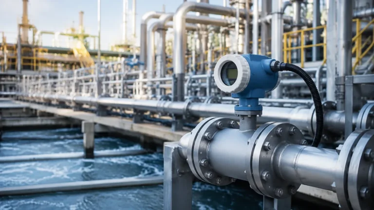
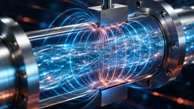
Hydraulic Pressure Transducer
Hydraulic Pressure Transducer
In the realm of industrial automation and fluid management, the hydraulic pressure transducer serves as a fundamental bridge between physical force and digital intelligence. These precision instruments are designed to convert the mechanical energy of a pressurized fluid into a standardized electrical signal, enabling real-time monitoring, control, and safety across a vast array of applications. From heavy machinery and aerospace systems to water treatment and chemical processing, the accuracy of these devices is paramount to operational efficiency.
For engineers and procurement professionals, understanding the nuances of transducer technology is essential. A hydraulic pressure transducer is not a one-size-fits-all component; its performance is dictated by the sensing principle, the materials used in construction, and the environment in which it operates. This guide provides a technical overview of these instruments, their application in level measurement, and the critical factors involved in their selection and installation.
Understanding the Measurement Principles
Before selecting a hydraulic pressure transducer, it is necessary to understand the underlying physical principles that allow these devices to function. Most modern transducers rely on the deformation of a sensing element—usually a diaphragm—under the influence of fluid pressure. This deformation is then measured using one of several technologies.
Piezoresistive Sensing
Piezoresistive transducers utilize the change in electrical resistance of a semiconductor (often silicon) when subjected to mechanical strain. These sensors are highly sensitive and can be miniaturized, making them ideal for high-precision applications. In a typical configuration, a silicon chip is bonded to a stainless steel diaphragm. When pressure is applied, the resistance changes proportionally, providing a robust signal. However, piezoresistive sensors are sensitive to temperature fluctuations and usually require internal compensation circuits.
Strain Gauge Technology
Strain gauge transducers are among the most common in industrial hydraulics. They consist of a fine wire or foil grid bonded to a flexible diaphragm. As the diaphragm flexes under pressure, the strain gauge stretches or compresses, altering its electrical resistance. These are often arranged in a Wheatstone bridge circuit to maximize sensitivity and stability. They are prized for their durability and ability to withstand high-pressure spikes, often found in heavy hydraulic equipment.
Capacitive Sensing
Capacitive transducers measure changes in electrical capacitance between a flexible diaphragm and a fixed backplate. As pressure moves the diaphragm closer to the plate, the capacitance increases. These sensors are known for their excellent stability and high resolution, particularly in low-pressure ranges. They are also inherently resistant to overpressure conditions because the diaphragm can only move until it hits the backplate, preventing permanent deformation.
The Role of Hydraulic Pressure Transducers in Level Measurement
While often associated with machinery, a hydraulic pressure transducer is a core component of hydrostatic level measurement. In this application, the sensor measures the "head pressure" exerted by a column of liquid. According to the laws of physics, the pressure at the bottom of a tank is directly proportional to the height of the liquid above it, provided the density remains constant.
The relationship is defined by the formula:
P = ρ × g × h
Where:
* P is the pressure (measured in Pascals or Bar).
* ρ (rho) is the density of the fluid (kg/m³).
* g is the gravitational constant (approx. 9.81 m/s²).
* h is the height of the liquid (meters).
By utilizing a high-accuracy hydraulic pressure transducer at the base of a vessel, operators can determine the exact fluid level without needing mechanical floats or complex optical systems. This method is particularly effective in deep wells, large reservoirs, and chemical storage tanks where top-down measurement might be obstructed. Welk offers a specialized range of these instruments designed to operate reliably in harsh industrial environments. For more detailed specifications on these systems, you can review product options and application support on our Main Page.
Key Evaluation Criteria for Selection
Choosing the right hydraulic pressure transducer requires a thorough evaluation of the process conditions and the required output. Failure to account for these variables can lead to premature sensor failure or inaccurate data.
1. Pressure Range and Overpressure Rating
The nominal pressure range should be selected so that the typical operating pressure falls within the middle 50% to 75% of the sensor’s capacity. This ensures longevity and accuracy. Furthermore, the "proof pressure" (the maximum pressure the sensor can withstand without damage) and "burst pressure" (the point of catastrophic failure) must be significantly higher than any potential system spikes.
2. Media Compatibility
The wetted parts of the transducer—those in direct contact with the fluid—must be chemically compatible with the media. While 316L stainless steel is standard for water and oil, more aggressive chemicals may require Hastelloy, Monel, or ceramic diaphragms. If the fluid is viscous or contains solids, a flush-diaphragm design is preferred to prevent clogging.
3. Output Signal and Communication
Industrial transducers typically offer several output options:
* 4-20 mA: The industry standard for long-distance transmission, as it is highly resistant to electrical noise.
* 0-10 V / 1-5 V: Common in localized control panels and laboratory settings.
* Digital (HART, RS485/Modbus): Allows for remote calibration, diagnostics, and the transmission of multiple variables (such as pressure and temperature).
4. Accuracy and Stability
Accuracy is usually expressed as a percentage of the Full Scale (FS). This includes errors from linearity, hysteresis, and repeatability. For critical process control, an accuracy of ±0.1% to ±0.25% FS is often required, whereas ±0.5% FS may suffice for general monitoring.
Selection Table: Comparing Transducer Technologies
| Feature | Piezoresistive | Strain Gauge | Capacitive |
| :— | :— | :— | :— |
| Best For | High Precision / Small Size | High Pressure / Durability | Low Pressure / Stability |
| Accuracy | Very High (±0.1% FS) | Moderate (±0.25% – 0.5% FS) | High (±0.1% FS) |
| Pressure Range | 0.1 Bar to 1000 Bar | 5 Bar to 5000+ Bar | 0.01 Bar to 40 Bar |
| Temp. Sensitivity | High (Requires compensation) | Low | Moderate |
| Cost | Mid-Range | Economical | Higher |
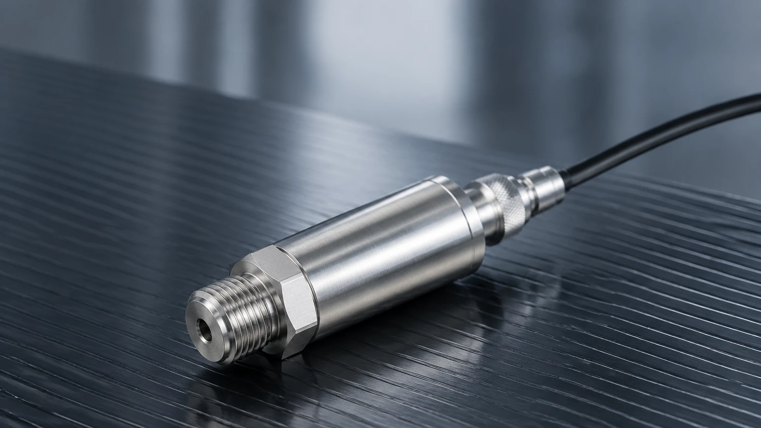
Installation and Configuration Guidelines
Proper installation is critical to the performance of a hydraulic pressure transducer. Even the most expensive sensor will provide poor data if installed incorrectly.
Mounting Orientation
While many transducers can be mounted in any orientation, low-pressure sensors may experience a "zero shift" if their orientation is changed after calibration. It is best to install the sensor in a vertical position to prevent the accumulation of air bubbles or sediment against the diaphragm.
Pressure Snubbers and Syphons
In hydraulic systems prone to rapid pressure pulses or water hammer, a pressure snubber should be installed. This device dampens the spikes, protecting the sensitive diaphragm from fatigue. For high-temperature steam or hot oil applications, a syphon or cooling tower should be used to ensure the fluid temperature at the sensor remains within its operating limits (typically < 85°C / 185°F).
Electrical Protection and Grounding
Transducers should be wired using shielded cables to prevent electromagnetic interference (EMI). In outdoor installations or areas prone to lightning, surge protection modules are highly recommended. For submersible level applications, ensure the atmospheric vent tube in the cable is kept clear and protected by a moisture-wicking filter.
Common Risks and Limitations
Despite their reliability, hydraulic pressure transducers face several challenges in industrial environments:
1. Temperature Drifts: Rapid changes in ambient or media temperature can cause the output signal to drift. Always check the "compensated temperature range" of the device.
2. Cavitation: In high-speed hydraulic circuits, cavitation can occur near the sensor, causing localized pressure spikes that can pit or crack the diaphragm.
3. Clogging: In wastewater or slurry applications, particles can build up in the pressure port. Using a flush-mount diaphragm or a chemical seal can mitigate this risk.
4. Long-term Drift: All sensors experience some degree of aging. Regular calibration (typically annually) is necessary to maintain system integrity.
Frequently Asked Questions (FAQs)
Q: What is the difference between a pressure transducer and a pressure transmitter?
A: Historically, a "transducer" referred to a device with a voltage output (e.g., 0-5V), while a "transmitter" referred to a device with a current output (4-20mA). Today, the terms are often used interchangeably in the industry.
Q: Can a hydraulic pressure transducer be used for gas measurement?
A: Yes, most hydraulic transducers are compatible with non-corrosive gases. However, the safety ratings and material compatibility must be verified, especially for oxygen or combustible gas service.
Q: How do I handle a sensor that is reading incorrectly at zero pressure?
A: This is often caused by mounting stress or temperature shifts. Most modern transmitters allow for a "zero trim" via a local button, a potentiometer, or digital communication (HART/Modbus) to reset the baseline.
Q: What cable length can I use for a 4-20mA transducer?
A: Because 4-20mA is a current loop, it can travel long distances—often up to 1,000 meters (approx. 3,280 ft)—with minimal signal loss, provided the power supply voltage is sufficient to overcome the loop resistance.
Conclusion
The hydraulic pressure transducer is an indispensable tool for modern engineering, providing the data necessary to manage complex fluid systems safely and efficiently. By carefully considering the measurement principle, environmental constraints, and installation requirements, engineers can ensure long-term reliability and accuracy. As a professional manufacturer, Welk continues to advance these technologies, offering customized solutions that meet the rigorous demands of global industrial automation. For assistance with specific application engineering or to view our full catalog, please visit our Main Page.