How to Test Pressure Transmitter
How to Test Pressure Transmitter
In industrial process control, the pressure transmitter is a fundamental component used to measure the pressure of liquids, gases, or steam. Whether it is used for direct pressure monitoring or as a proxy for level and flow measurement, the accuracy of these devices is paramount. For engineers and maintenance technicians, knowing how to test pressure transmitter units is a critical skill that ensures plant safety, operational efficiency, and product quality.
Welk, a professional manufacturer of industrial level measurement instruments, emphasizes that regular verification and calibration are necessary to counteract the natural "drift" that electronic sensors experience over time. This guide provides a comprehensive technical overview of the principles, procedures, and selection criteria for pressure transmitters in B2B environments such as water treatment, chemical processing, and oil and gas.
Understanding Pressure Measurement Principles
Before diving into the testing procedures, it is essential to understand how these devices function. A pressure transmitter converts a mechanical pressure force into a standardized electrical signal, typically 4-20mA.
The Transducer Element
Most modern transmitters utilize one of three primary sensing technologies:
1. Piezoresistive Sensors: These use a silicon diaphragm with integrated resistors. When pressure is applied, the diaphragm deforms, changing the electrical resistance (the piezoresistive effect).
2. Capacitive Sensors: These measure the change in capacitance between a sensing diaphragm and a fixed capacitor plate. As pressure moves the diaphragm, the capacitance changes proportionally.
3. Hydrostatic Principles: In level measurement applications, pressure transmitters (often called hydrostatic level transmitters) measure the pressure exerted by a liquid column. The pressure at the bottom of a tank is directly proportional to the height of the liquid and its density ($P = \rho \cdot g \cdot h$).
By understanding these principles, technicians can better diagnose whether a failure is due to a mechanical breach of the diaphragm or an electronic failure in the signal processing circuit.
Essential Tools for Testing
To perform a valid test, you must have calibrated reference equipment that is significantly more accurate than the device under test (DUT). Usually, a 4:1 accuracy ratio is recommended.
* Digital Multimeter (DMM): Used to measure the 4-20mA output signal. It must have high precision (at least 5.5 digits recommended).
* Pressure Source: This could be a manual hand pump (pneumatic or hydraulic) or a deadweight tester for high-precision laboratory environments.
* Digital Pressure Gauge/Calibrator: A reference standard to verify the actual pressure being applied by the source.
* Power Supply: Most transmitters are loop-powered and require 24V DC.
* HART Communicator: For smart transmitters, a HART (Highway Addressable Remote Transducer) modem or handheld device is required to read internal diagnostics and adjust configuration parameters.
How to Test Pressure Transmitter: Step-by-Step Procedure
Testing can be performed in the field (in-situ) or on a laboratory bench. For a full calibration check, the bench test is preferred as it eliminates process variables like vibration or temperature fluctuations.
1. Safety and Isolation
If the transmitter is installed in a live process, you must follow Lockout/Tagout (LOTO) procedures. Close the isolation valves and bleed any trapped pressure through the vent valve. Ensure the medium is safely drained, especially if dealing with hazardous chemicals.
2. The Setup
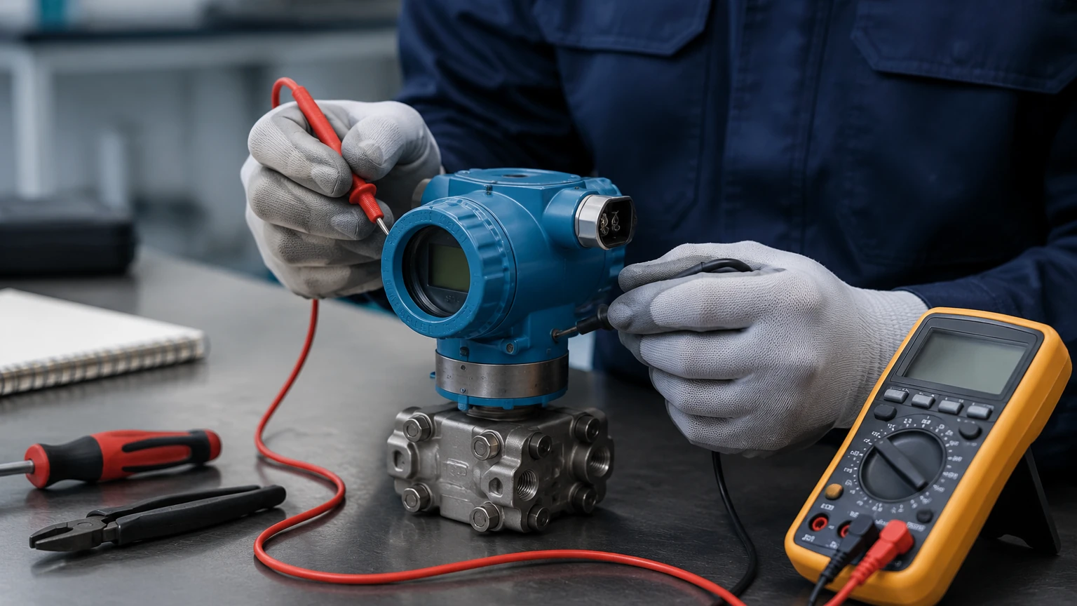
Connect the pressure source to the high-pressure port of the transmitter. Connect the multimeter in series with the 24V DC power supply and the transmitter’s output terminals to measure the current loop. If using a HART communicator, connect it across a 250-ohm resistor in the loop.
3. Zero Point Check
With no pressure applied (atmospheric pressure), the transmitter should output exactly 4.000mA. If the reading is slightly off (e.g., 4.05mA), this is known as a zero shift. Many industrial units allow for a "Zero Trim" via an external button or HART command.
4. Five-Point Calibration Test
To evaluate the linearity and accuracy of the transmitter, perform a five-point check. This involves applying pressure at specific increments of the calibrated range:
* 0% (Lower Range Value): 4.00mA
* 25%: 8.00mA
* 50%: 12.00mA
* 75%: 16.00mA
* 100% (Upper Range Value): 20.00mA
Record the actual milliamp output at each stage. For the most thorough test, perform these steps both ascending (0 to 100%) and descending (100 to 0%) to check for hysteresis—the difference in readings when approaching a point from different directions.
5. Calculating Error
The error is calculated using the formula:
$$\text{Error (\%)} = \left( \frac{\text{Measured mA} – ext{Theoretical mA}}{16} \right) \times 100$$
If the error exceeds the manufacturer’s specified tolerance (e.g., ±0.1% or ±0.25% of span), the transmitter requires calibration or replacement.
Selection Table for Pressure and Level Transmitters
Choosing the right instrument is the first step in ensuring long-term reliability. Below is a comparison of common industrial level and pressure measurement technologies available for various applications.
| Technology | Typical Application | Advantages | Limitations |
| :— | :— | :— | :— |
| Hydrostatic Transmitter | Water tanks, deep wells | Cost-effective, simple installation | Sensitive to density changes |
| Radar Level Meter | Chemical reactors, solids | Non-contact, high accuracy | Higher initial cost |
| Ultrasonic Sensor | Open channels, wastewater | Non-contact, low maintenance | Affected by foam and steam |
| Differential Pressure | Flow measurement, pressurized tanks | Versatile, well-understood | Requires impulse lines |
| Magnetic Level Gauge | High-pressure boilers | Highly visible, no power needed | Mechanical parts can wear |
For detailed specifications on these technologies, you can review product options and application support on the Main Page.
Installation and Maintenance Considerations
Even a perfectly tested transmitter will fail if installed incorrectly. Follow these engineering best practices:
* Impulse Piping: For gas applications, the transmitter should be mounted above the process tap to allow condensate to drain back. For liquid applications, mount it below the tap to ensure air bubbles can escape.
* Environmental Protection: While many Welk transmitters feature IP67 or IP68 ratings, using a sunshade or protective housing can extend the life of the electronics in extreme climates.
* Seal Integrity: Ensure that O-rings and process connections are compatible with the medium. In chemical industries, PTFE or Hastelloy diaphragms may be necessary to prevent corrosion.
* Damping Settings: If the process pressure fluctuates rapidly (pulsation), adjust the electronic damping (usually measured in seconds) to smooth the output signal and prevent "chatter" in the control system.
Common Risks and Limitations
When learning how to test pressure transmitter performance, it is important to recognize the factors that can lead to false readings:
1. Temperature Effects: Significant shifts in ambient temperature can cause the fill fluid inside the transmitter to expand or contract, resulting in a "thermal span shift."
2. Overpressure Events: If a transmitter is exposed to pressure beyond its "Proof Pressure" rating, the diaphragm may be permanently deformed, leading to non-linear errors that cannot be calibrated out.
3. Clogging: In wastewater or slurry applications, the pressure port can become blocked. Using a flush diaphragm transmitter is often the recommended solution for these environments.
4. Loop Resistance: Ensure the total resistance of the 4-20mA loop (including wires and controller input) does not exceed the transmitter's maximum load capacity, which is typically around 500 to 600 ohms at 24V DC.
Frequently Asked Questions (FAQs)
Q: How often should I test my pressure transmitter?
A: For most industrial applications, an annual calibration check is standard. However, in critical safety loops (SIL-rated), testing may be required every 3 to 6 months.
Q: Can I test a transmitter without a pressure pump?
A: You can perform a "Loop Test" to check the wiring and the DCS/PLC input by forcing the transmitter to output a specific mA signal via a HART communicator. However, this does not test the actual sensing diaphragm.
Q: What is the difference between a 2-wire and 4-wire transmitter?
A: A 2-wire transmitter uses the same two wires for both power and the 4-20mA signal. A 4-wire transmitter has separate pairs for power (often 110V/220V AC or 24V DC) and the signal output.
Q: Why is my transmitter reading 3.8mA or 20.5mA?
A: Most transmitters use NAMUR NE43 standards to signal a fault. A reading below 3.8mA or above 20.5mA usually indicates a sensor failure or a hardware error.
Conclusion
Mastering how to test pressure transmitter units is essential for maintaining the integrity of industrial processes. By following a structured five-point calibration procedure, using the correct reference tools, and understanding the underlying measurement principles, technicians can ensure that their instrumentation provides the reliable data needed for automation and safety.
Welk continues to provide high-quality, cost-effective level and pressure measurement solutions designed for the rigors of modern industry. For those looking to upgrade their current systems or seeking specialized OEM/ODM services, visiting the Main Page offers access to a wide range of radar, ultrasonic, and hydrostatic instruments tailored to specific application needs.