Ultrasonic Level Indicator
Ultrasonic Level Indicator
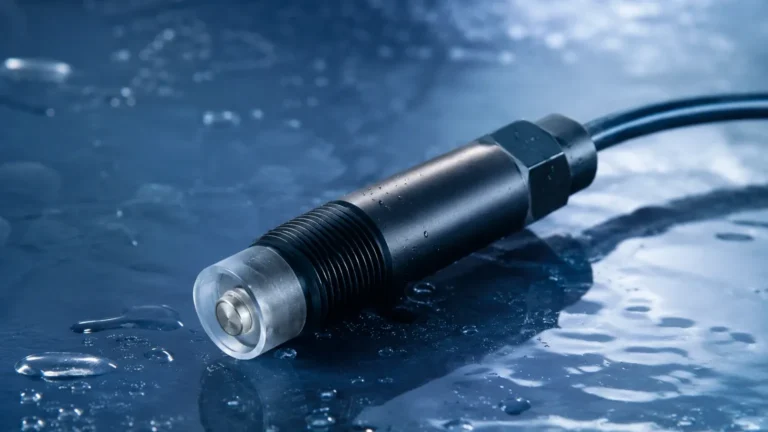
In the landscape of industrial process control, the ultrasonic level indicator has established itself as a cornerstone technology for non-contact level measurement. By utilizing high-frequency sound waves to determine the distance to a liquid or solid surface, these instruments provide a reliable, maintenance-free solution for monitoring inventory and controlling processes across a wide range of industries. As a professional manufacturer, Welk specializes in delivering these advanced level measurement instruments to sectors including water treatment, chemical processing, and industrial automation.
Understanding the technical nuances, installation requirements, and environmental limitations of an ultrasonic level indicator is essential for engineers and plant managers seeking to optimize their operations. This guide provides a comprehensive technical overview to assist in the selection and implementation of ultrasonic technology.
Measurement Principle: The Physics of Sound
Before selecting an instrument, it is vital to understand the underlying Time-of-Flight (ToF) principle that governs ultrasonic level measurement. The ultrasonic level indicator functions by emitting a series of ultrasonic pulses from a transducer located at the top of a vessel or above an open channel.
The Time-of-Flight (ToF) Calculation
These sound pulses travel through the air or gas space, reflect off the surface of the medium (liquid or solid), and return to the transducer. The instrument’s internal electronics measure the time interval between the transmission of the pulse and the reception of the echo. The distance ($D$) from the sensor to the surface is calculated using the formula:
$$D = \frac{v \times t}{2}$$
Where:
* $v$ is the speed of sound in the medium (typically air).
* $t$ is the total time elapsed for the pulse to travel to the surface and back.
The level of the material ($L$) is then determined by subtracting the measured distance ($D$) from the total height of the tank or vessel ($H$):
$$L = H – D$$
Compensation for Environmental Variables
The speed of sound is not constant; it varies primarily with the temperature of the gas through which it travels. In air, the speed of sound increases by approximately 0.6 meters per second for every degree Celsius increase in temperature. To maintain accuracy, a high-quality ultrasonic level indicator incorporates an integrated temperature sensor to provide real-time compensation for these fluctuations. For more complex applications or product specifications, engineers can consult the Main Page for detailed technical data sheets.
Key Evaluation Criteria for Selection
Selecting the correct ultrasonic level indicator requires a detailed analysis of the application environment. Unlike contact-based methods, ultrasonic sensors are sensitive to the atmosphere between the sensor and the target.
1. Measuring Range and Dead Zone
Every ultrasonic sensor has a minimum distance requirement known as the "dead zone" or "blocking distance." This is the area immediately below the transducer face where the sensor cannot accurately process returning signals because the transducer is still vibrating from the initial transmission. Typical dead zones range from 0.2 meters (0.66 ft) to 0.5 meters (1.64 ft), depending on the frequency of the sensor. The maximum range must also be considered, as sound energy dissipates over distance.
2. Beam Angle and Vessel Geometry
The ultrasonic pulse is transmitted in a cone-shaped beam. The beam angle (usually between 5° and 12°) determines the footprint of the signal at a specific distance. If the beam is too wide, it may encounter internal obstructions such as ladders, pipes, or agitators, leading to false echoes. Conversely, a narrow beam is often required for tall, thin silos or tanks with complex internal structures.
3. Material Characteristics
Ultrasonic waves reflect best off hard, flat surfaces. Liquids generally provide an excellent reflective surface. However, granular solids (like grain or plastic pellets) may scatter the sound waves, requiring a sensor with higher power or a specialized aiming flange. Furthermore, heavy foam on a liquid surface can absorb the ultrasonic signal entirely, leading to a "lost echo" condition.
Practical Selection Table
The following table outlines typical specifications for industrial-grade ultrasonic level indicators used in various process environments.
| Feature | Standard Liquid Application | Long-Range / Solids Application | High-Precision / Chemical |
| :— | :— | :— | :— |
| Measuring Range | 0.4m to 10m (1.3ft to 33ft) | 0.8m to 30m (2.6ft to 98ft) | 0.25m to 6m (0.8ft to 20ft) |
| Accuracy | ±0.25% to ±0.5% of range | ±0.5% of range | ±2mm or ±0.1% of range |
| Beam Angle | 10° to 12° | 5° to 8° | 6° to 10° |
| Output Signal | 4-20mA, HART | 4-20mA, RS485/Modbus | 4-20mA, HART, Profibus |
| Housing Material | ABS / PVC | Aluminum Alloy / Stainless Steel | PVDF / PTFE (Corrosion Resistant) |
| Protection Class | IP66 / IP67 | IP67 / IP68 | IP68 / Explosion-proof |
| Process Temp. | -20°C to +60°C | -40°C to +80°C | -40°C to +95°C |
Installation Considerations and Best Practices
Proper installation is the most critical factor in ensuring the long-term reliability of an ultrasonic level indicator. Errors in mounting often lead to intermittent signal loss or inaccurate readings.
Mounting Position
* Avoid the Center: In cylindrical tanks with domed tops, do not mount the sensor in the exact center. This can create a focal point for multiple reflections, leading to signal interference.
* Stay Away from Inlets: Never install the sensor directly above the fill stream. The falling material will obstruct the ultrasonic pulse and cause erratic readings.
* Wall Clearance: Ensure the beam path is clear of the tank wall. A general rule is to maintain a distance from the wall equal to at least 1/10th of the total tank height.
Orientation
The transducer face must be mounted perfectly parallel to the surface of the medium. Even a slight tilt can cause the reflected signal to miss the transducer, especially at longer distances. For solids applications where the material forms a conical pile, an adjustable swivel flange is recommended to aim the sensor perpendicular to the slope of the material.
Standpipes and Nozzles
If the sensor must be mounted on a nozzle, the nozzle diameter must be large enough to accommodate the beam angle, and the inner surface of the nozzle should be smooth. If the nozzle is too long or narrow, the pulse may reflect off the nozzle edges before reaching the process medium.

Limitations and Common Risks
While ultrasonic technology is versatile, certain process conditions can compromise its effectiveness. Engineers should evaluate these risks during the project planning phase:
1. Vapor and Steam: High concentrations of heavy vapors or steam can change the density of the gas space, significantly altering the speed of sound and introducing measurement errors. In such cases, radar level meters may be a more appropriate choice.
2. Pressure Extremes: Ultrasonic sensors are generally limited to near-atmospheric pressure. High pressure increases the density of the gas, which can affect the transducer’s ability to vibrate effectively. Most ultrasonic indicators are rated for a maximum pressure of 0.3 MPa (3 bar).
3. Vacuum Conditions: Sound requires a medium to travel. In a vacuum, ultrasonic pulses cannot propagate, making this technology unusable.
4. Acoustic Noise: High-frequency noise from pneumatic conveying or heavy machinery can occasionally interfere with the sensor’s frequency, though modern digital filtering (DSP) has mitigated much of this risk.
Frequently Asked Questions (FAQs)
Q: Can an ultrasonic level indicator be used for measuring the level of acids?
A: Yes, provided the sensor is constructed from chemically resistant materials such as PVDF or PTFE. It is important to ensure that the fumes from the acid do not condense on the transducer face, as droplets can attenuate the signal.
Q: How does wind affect an outdoor ultrasonic measurement?
A: Strong wind can "blow" the ultrasonic pulse away or create turbulence in the air, leading to signal instability. For outdoor installations, such as open channel flow measurement in weirs or flumes, a sunshade or protective shroud is recommended to stabilize the local environment around the sensor.
Q: What happens if the level enters the dead zone?
A: If the material rises into the dead zone, the instrument will typically output an error signal or hold the last known valid reading. It is critical to mount the sensor high enough so that the maximum possible liquid level never reaches the blocking distance.
Q: Is calibration required for different liquids?
A: Generally, no. Since the measurement is based on the distance to the surface and the speed of sound through air, the specific gravity or dielectric constant of the liquid does not affect the measurement, unlike hydrostatic or capacitive sensors.
Conclusion and Project Confirmation
The ultrasonic level indicator remains a premier choice for B2B applications requiring non-contact, cost-effective, and reliable level monitoring. By adhering to strict installation guidelines and understanding the environmental factors that influence sound propagation, industrial users can achieve high levels of process transparency.
Before proceeding with an order, project teams should confirm the following:
* The maximum and minimum expected levels relative to the sensor mounting point.
* The presence of foam, steam, or heavy dust in the vessel.
* The internal geometry and potential obstructions within the beam path.
* Required communication protocols (e.g., 4-20mA, Modbus, or HART).
For further technical support and to review specific product options, visit the Main Page to connect with application engineers who can provide customized solutions for your specific industrial requirements.