Radar Level Transmitter Measuring Range
Understanding Radar Level Transmitter Measuring Range: An Engineering Guide
In industrial process automation, selecting the correct instrumentation requires a deep understanding of how physical constraints interact with sensor technology. Among the various methods for liquid and solid level detection, Radar Level Meters have become the industry standard due to their non-contact nature and high precision. However, the performance of these devices is strictly governed by the radar level transmitter measuring range, a parameter that is influenced by frequency, dielectric properties, and vessel geometry.
This guide examines the technical principles behind radar measurement, the factors that define the effective range, and practical selection criteria for engineering professionals.
1. Measurement Principles and Technology Types
Before specifying a measuring range, it is essential to understand the two primary technologies used in radar level transmitters: Pulse Radar and Frequency Modulated Continuous Wave (FMCW).
1.1 Pulse Radar (Time of Flight)
Pulse radar transmitters emit short microwave pulses toward the material surface. The device measures the time it takes for the pulse to travel to the surface and reflect back to the sensor. This "Time of Flight" (ToF) is directly proportional to the distance. While effective for many applications, pulse radar typically has a lower signal-to-noise ratio compared to FMCW, which can limit its maximum effective range in environments with heavy foam or turbulence.
1.2 FMCW Radar (Frequency Modulated Continuous Wave)
FMCW technology is the preferred choice for high-precision and long-range applications. Instead of pulses, the transmitter emits a continuous signal with a constantly changing frequency. The reflection from the product surface is received and compared to the emitted signal. The frequency difference between the transmitted and received signals is proportional to the distance.
Modern FMCW transmitters, particularly those operating at 80GHz, offer a significantly wider radar level transmitter measuring range—often reaching up to 120 meters (approx. 393 ft)—due to their superior signal processing and narrower beam angles.
2. Defining the Measuring Range: The Blind Zone and Maximum Distance
The measuring range of a radar transmitter is not simply the distance from the sensor to the bottom of the tank. It is defined by two critical boundaries: the Upper Blind Zone (Dead Zone) and the Maximum Measuring Distance.
2.1 The Upper Blind Zone
The blind zone is the area immediately below the antenna where the device cannot accurately process reflections. This occurs because the transmitter cannot distinguish between the outgoing signal and the incoming reflection when the surface is too close.
* Typical Blind Zone: 50mm to 500mm (2 in to 20 in), depending on the antenna type and frequency.
* Engineering Impact: If the liquid level enters the blind zone, the transmitter may output an error signal or hold the last known value. Engineers must ensure the maximum fill level of the tank remains below this threshold.
2.2 Maximum Measuring Distance
This is the furthest distance the radar can reliably detect a surface. While a datasheet might specify a range of 30m or 100m, this is often calculated based on an ideal reflective surface (like water). In practice, the maximum range is limited by the signal's attenuation and the reflective properties of the media.
3. Factors Influencing the Effective Measuring Range
Several variables determine whether a transmitter can reach its theoretical maximum range in a specific application.
3.1 Dielectric Constant ($ε_r$)
The dielectric constant of the medium is the most significant factor in signal reflection.
* High $ε_r$ (e.g., Water, $ε_r ≈ 80$): Reflects almost all the radar energy, allowing for the maximum possible measuring range.
* Low $ε_r$ (e.g., Hydrocarbons, $ε_r < 2.0$): Much of the signal penetrates the material rather than reflecting. This results in a weaker echo, which effectively reduces the reliable radar level transmitter measuring range.
3.2 Frequency and Beam Angle
The frequency of the radar (typically 6GHz, 26GHz, or 80GHz) dictates the beam angle.
* 6GHz to 26GHz: These lower frequencies have wider beam angles. They are robust against steam and dust but are more likely to hit internal tank obstructions (agitators, ladders), which can create "false echoes" that limit the usable range.
* 80GHz: These high-frequency units have very narrow beam angles (as low as 3°). This focuses the energy on the product surface, allowing for longer ranges in narrow vessels and better performance with low-dielectric materials.
3.3 Surface Conditions
Turbulence, ripples, or heavy foam can scatter the radar signal. In the case of solids, the "angle of repose" (the slope of the material pile) can reflect the signal away from the antenna, necessitating a transmitter with a higher sensitivity or a larger antenna to maintain the required range.
4. Practical Selection Table
The following table provides a general guideline for matching radar technology to required measuring ranges and applications.
| Technology | Typical Frequency | Max Theoretical Range | Common Applications | Key Limitation |
| :— | :— | :— | :— | :— |
| Pulse Radar | 6GHz – 26GHz | 30m (98 ft) | Simple liquid storage, large tanks | Sensitive to foam/turbulence |
| FMCW Radar | 26GHz | 70m (230 ft) | Corrosive liquids, solids silos | Wider beam may hit obstructions |
| High-Freq FMCW | 80GHz | 120m (393 ft) | Narrow vessels, tall silos, low $ε_r$ | Higher initial cost |
| Guided Wave Radar | N/A | 30m – 60m | Interface measurement, bypass pipes | Contacting (probe can break) |
5. Installation Considerations for Range Optimization
To ensure the Radar Level Meters achieve their specified radar level transmitter measuring range, proper installation is mandatory.
1. Avoid the Center: Do not install the transmitter in the exact center of a domed tank. This can cause multiple reflections that interfere with the primary echo.
2. Distance from Wall: Maintain a minimum distance from the tank wall (typically 1/10th of the tank height) to prevent side-wall interference.
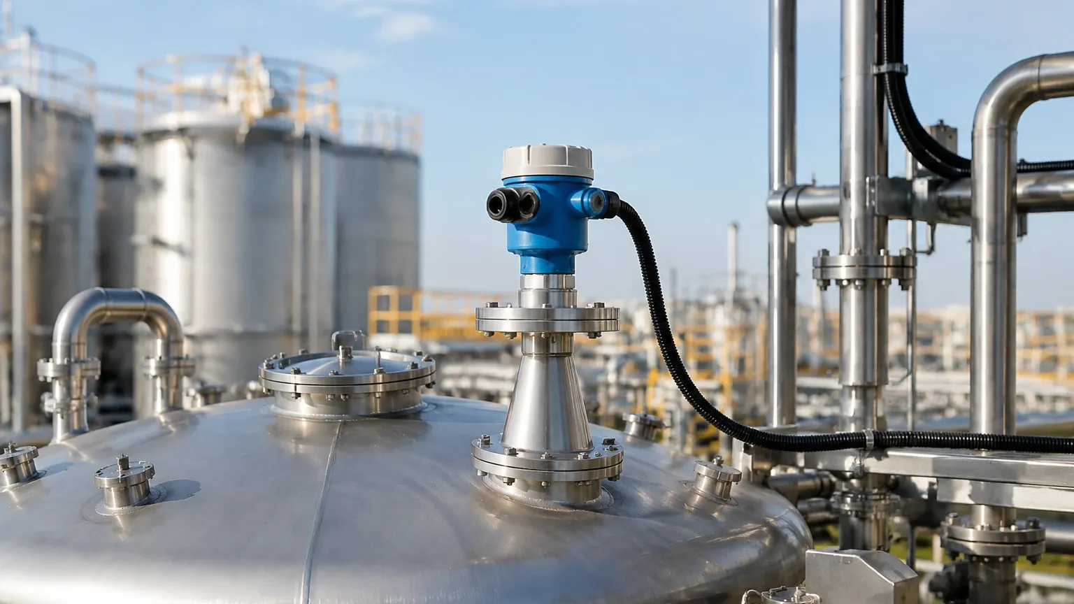
3. Nozzle Height: The antenna should ideally extend beyond the mounting nozzle. If the antenna is recessed deep within a nozzle, signal ringing can occur, increasing the size of the blind zone.
4. Obstruction Mapping: Use the transmitter's software to perform a "False Echo Suppression" or "Static Background Masking." This tells the sensor to ignore reflections from fixed objects like agitator blades or support beams, effectively cleaning up the signal over the entire measuring range.
6. Application Risks and Limitations
While radar is highly versatile, engineers must be aware of specific limitations that can compromise the measuring range:
* Heavy Foam: Some foams are "transparent" to radar, while others are highly absorbent. If the foam absorbs the signal, the transmitter may lose the echo entirely.
* Dust and Condensation: While 80GHz radar handles dust well, extreme build-up on the antenna lens can attenuate the signal. In such cases, transmitters with integrated air-purge connections are recommended to keep the lens clean and maintain the range.
* Vacuum and Pressure: While radar works in a vacuum, extreme high-pressure steam can slightly change the speed of the microwave signal, leading to small measurement errors, though the range remains largely unaffected.
7. Frequently Asked Questions (FAQ)
Q: Can I use a radar transmitter with a 100m range in a 5m tank?
A: Yes. Using a device with a longer potential range often means it has a higher signal-to-noise ratio, which can provide more stable readings even in small tanks with challenging conditions.
Q: How does the dielectric constant affect the accuracy at the end of the range?
A: As the distance increases, the signal strength drops (Inverse Square Law). If the material has a low dielectric constant, the reflection might become too weak for the sensor to distinguish from background noise as it approaches the maximum distance.
Q: Does the temperature of the medium affect the measuring range?
A: No. Unlike ultrasonic sensors, radar waves are electromagnetic and do not require a medium (air) to travel. Therefore, temperature gradients in the tank do not affect the speed of the signal or the measuring range.
8. Conclusion
Selecting the appropriate radar level transmitter measuring range involves more than just matching tank height to a datasheet value. Engineers must account for the dielectric properties of the media, the physical constraints of the vessel, and the specific radar frequency used. By choosing high-frequency FMCW technology and following rigorous installation standards, industrial operators can ensure reliable, maintenance-free level measurement even in the most demanding environments.
For technical specifications on specific models and assistance with application engineering, professionals should consult updated documentation on Radar Level Meters to ensure the chosen instrument meets the operational requirements of the facility.