Flow Meters for Slurry
Flow Meters for Slurry
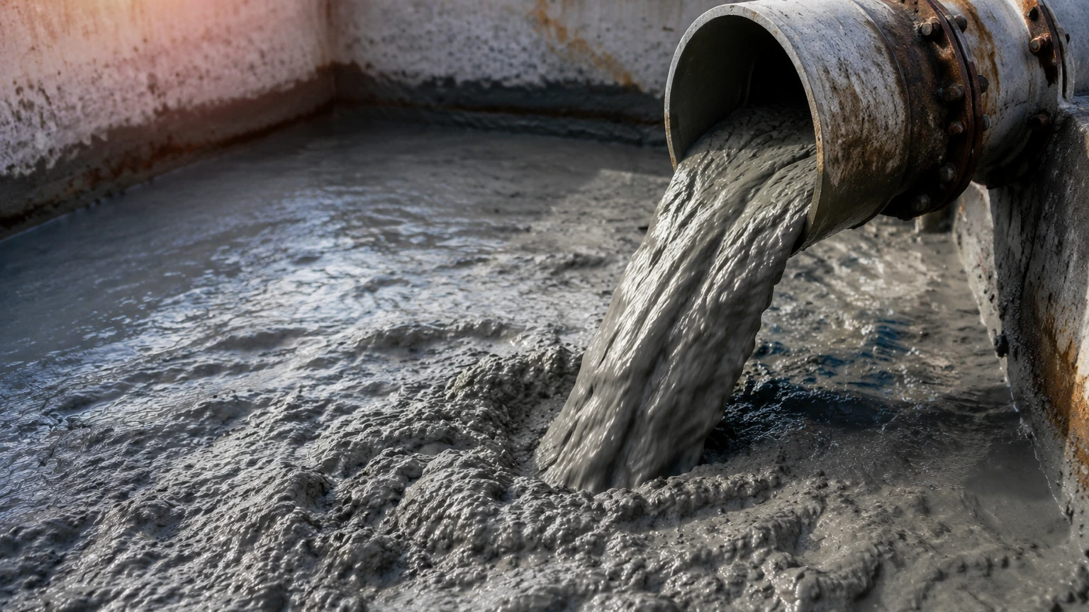
In industrial process engineering, slurry measurement represents one of the most challenging applications for flow instrumentation. A slurry is a multi-phase mixture consisting of a carrier liquid—typically water or a chemical solvent—and suspended solid particles. These particles can range from fine silts to coarse, abrasive ores. Selecting the correct flow meters for slurry is critical for maintaining process efficiency, protecting downstream equipment, and ensuring accurate mass balance in mining, wastewater treatment, and chemical processing plants.
Because slurries are inherently abrasive and often corrosive, standard flow meters used for clean liquids often fail prematurely or provide inaccurate readings. This guide explores the principles of slurry flow measurement, material considerations, and technical selection criteria required for reliable operation.
Understanding Slurry Flow Dynamics
Before selecting an instrument, it is essential to understand how slurries behave within a pipeline. Unlike clean liquids, slurries can exhibit non-Newtonian behavior, where viscosity changes depending on the shear rate. Furthermore, the distribution of solids is rarely uniform.
In a horizontal pipe, solids tend to settle toward the bottom if the flow velocity is too low. This creates a "stratified" flow or a moving bed, which can cause significant measurement errors and pipe blockages. Conversely, excessively high velocities lead to accelerated erosion of the flow meter’s internal components. The "critical carrying velocity" is the minimum speed required to keep particles in suspension, and flow meters must be sized to operate above this threshold while remaining within the instrument's optimal sensing range.
Primary Measurement Principles for Slurry Applications
Several technologies are utilized to measure slurry flow, each relying on different physical principles. The choice depends on the conductivity of the fluid, the concentration of solids, and the required accuracy.
Electromagnetic Flow Meters (Magmeters)
Electromagnetic flow meters are the industry standard for conductive slurries. They operate based on Faraday’s Law of Induction, which states that a conductor (the slurry) moving through a magnetic field generates a voltage proportional to its velocity.
* Principle: The meter consists of a non-conductive liner and a pair of electrodes. As the slurry flows through the magnetic field generated by the meter’s coils, a voltage is induced. Because the meter has no moving parts and no obstructions in the flow path, it is highly resistant to wear and does not cause a pressure drop.
* Requirement: The carrier liquid must have a minimum conductivity, typically >5 μS/cm.
Ultrasonic Doppler Flow Meters
For applications where a non-intrusive solution is required, Doppler ultrasonic meters are used. These are "clamp-on" devices that do not require cutting the pipe.
* Principle: The meter transmits an ultrasonic signal into the pipe. The signal reflects off the moving solid particles or entrained gas bubbles. Due to the Doppler effect, the frequency of the reflected signal shifts. The meter calculates the flow velocity based on this frequency shift.
* Requirement: There must be a sufficient concentration of particles (usually >100 ppm) to reflect the signal, and the slurry must be moving fast enough to keep these particles in suspension.
Coriolis Mass Flow Meters
While more expensive, Coriolis meters provide direct mass flow and density measurements, which are invaluable for determining the dry solids content of a slurry.
* Principle: The slurry passes through vibrating tubes. The mass of the moving fluid causes a slight twisting of the tubes (the Coriolis effect), which is measured by sensors. The phase shift between the vibrations is proportional to the mass flow rate.
* Requirement: Coriolis meters for slurry must be designed with thick-walled tubes to withstand erosion and are typically used for high-value slurries where density monitoring is critical.
Material Selection and Wear Resistance
In slurry applications, the longevity of the flow meter is determined by its material composition. The internal surfaces must withstand constant bombardment by solid particles.
Liner Materials
For electromagnetic meters, the liner protects the outer housing and provides electrical insulation. Common choices include:
1. Polyurethane: Excellent for abrasive slurries at ambient temperatures. It is highly resilient against impact from large particles.
2. PTFE/PFA (Teflon): Best for corrosive chemical slurries. While chemically inert, these materials are softer and may wear faster in high-velocity abrasive applications.
3. Ceramic: Offers the highest resistance to both abrasion and corrosion. Ceramic liners are ideal for ore processing but are brittle and sensitive to thermal shock.
Electrode Materials
Electrodes must remain in contact with the slurry to pick up the induced voltage. In abrasive environments, "bullet-shaped" or recessed electrodes are often used to minimize turbulence and wear. Common materials include Stainless Steel 316L, Hastelloy C, Tantalum, and Tungsten Carbide.
Selection Guide for Slurry Flow Meters
The following table provides a general comparison of technologies used for slurry measurement:
| Feature | Electromagnetic | Ultrasonic (Doppler) | Coriolis |
| :— | :— | :— | :— |
| Accuracy | ±0.5% of rate | ±2% to ±5% of rate | ±0.1% to ±0.5% of rate |
| Installation | Inline (Flanged) | Clamp-on | Inline (Flanged/Welded) |
| Solids Content | Up to 70% | 1% to 40% | Up to 80% |
| Abrasive Resistance | High (with proper liner) | Excellent (Non-contact) | Moderate (Tube wear) |
| Conductivity Req. | Yes (>5 μS/cm) | No | No |
| Pressure Drop | None | None | Low to Moderate |
Installation and Maintenance Best Practices
Correct installation is as important as instrument selection for ensuring the accuracy of flow meters for slurry.
Pipe Orientation
Vertical installation with upward flow is the preferred orientation for slurry measurement. This ensures that the pipe is always full and that the solids are distributed as uniformly as possible across the pipe cross-section. If horizontal installation is unavoidable, the electrodes of a magmeter should be positioned at the 3 o'clock and 9 o'clock positions to prevent them from being covered by settled solids at the bottom or air bubbles at the top.
Straight Run Requirements
To ensure a stable flow profile, flow meters typically require a straight run of pipe upstream (usually 5 to 10 pipe diameters) and downstream (2 to 5 pipe diameters) from the meter. Slurry turbulence caused by elbows or valves can lead to erratic readings and localized erosion.
Grounding
For electromagnetic meters, proper grounding is mandatory. In plastic-lined or non-conductive pipes, grounding rings must be installed to ensure the fluid is at the same electrical potential as the meter body. Without proper grounding, electrical noise will interfere with the low-voltage signal generated by the flow.
Maintenance
Slurry meters should be inspected periodically for liner wear and electrode coating. In some chemical slurries, a film can build up on the electrodes, insulating them from the fluid. Some modern magmeters include "electrode cleaning" circuits that use high-frequency pulses to break off these deposits.
Common Risks and Operational Limitations
Despite advancements in technology, slurry measurement faces several inherent risks:
* Signal Noise: Large particles hitting the electrodes in a magmeter can create "slurry noise," which appears as rapid fluctuations in the flow reading. High-frequency excitation or specialized signal processing is often required to filter this noise.
* Liner Vacuum: In certain piping configurations, a vacuum can form (e.g., when a pump is shut off). If the liner is not properly bonded to the meter body, the vacuum can collapse or tear the liner.
* Erosion-Corrosion Synergy: In many mineral processing applications, the slurry is both abrasive and acidic. The abrasive particles strip away the protective oxide layer on metal components, allowing corrosion to proceed much faster than it would in a clean liquid.
Integrating Flow and Level Measurement
In many industrial plants, flow measurement is only one part of the control strategy. For instance, in a flotation cell or a thickener tank, flow meters monitor the input and output, while level sensors monitor the volume within the vessel. For comprehensive instrumentation solutions, including level and flow monitoring, engineers can visit the Main Page for technical specifications and application support.
Welk provides a range of level measurement instruments, such as radar and ultrasonic sensors, that complement slurry flow systems by providing real-time data on tank levels and sump volumes, preventing overflows and pump cavitation.
Frequently Asked Questions (FAQ)
Q: Can I use a vortex flow meter for slurry?
A: No. Vortex meters rely on a bluff body to create pressure oscillations. In a slurry, the solid particles will quickly erode the bluff body, and the solids can clog the sensors, leading to total failure.
Q: What velocity should I maintain for slurry flow?
A: Generally, a velocity between 1.5 m/s and 3.0 m/s (approx. 5 to 10 ft/s) is ideal. This is usually high enough to prevent settling but low enough to minimize pipe and meter wear.
Q: How do I measure the flow of a non-conductive slurry?
A: If the carrier liquid is non-conductive (like oil), an electromagnetic meter will not work. In these cases, Coriolis mass flow meters or Doppler ultrasonic meters are the best alternatives.
Q: How often should I calibrate a slurry flow meter?
A: Calibration frequency depends on the abrasiveness of the slurry. In highly abrasive mining applications, a yearly check is recommended to ensure that internal wear has not significantly altered the meter's cross-sectional area or sensing accuracy.
Summary of Confirmation Steps
Before finalizing the purchase of flow meters for slurry, project engineers should confirm the following data points:
1. Fluid Conductivity: Is the carrier liquid conductive enough for a magmeter?
2. Solids Characteristics: What is the maximum particle size and the percentage of solids by weight?
3. Chemical Compatibility: Will the liner and electrodes withstand the pH and chemical additives in the slurry?
4. Flow Range: Does the expected flow rate stay above the settling velocity and below the excessive erosion velocity?
5. Installation Geometry: Is there a vertical pipe run available for the most accurate measurement?
By addressing these factors during the design phase, industrial facilities can ensure long-term reliability and accurate data from their slurry flow measurement systems.