Optical Turbidity Sensor
Optical Turbidity Sensor
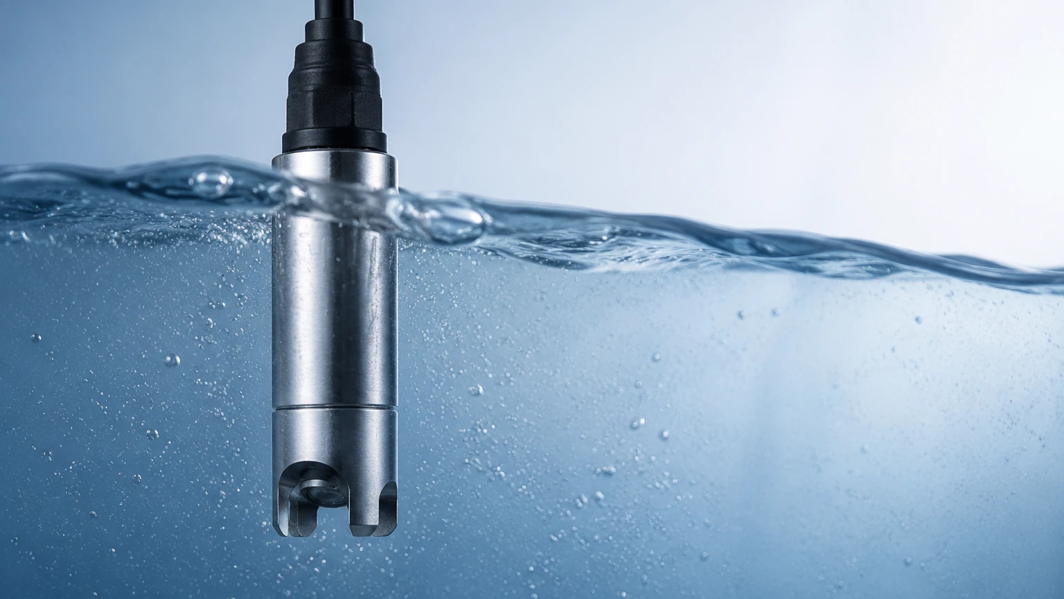
In industrial process control and environmental monitoring, the optical turbidity sensor serves as a critical instrument for quantifying the clarity of liquids. Turbidity is not a direct measure of the concentration of suspended particles but rather an expression of the optical property that causes light to be scattered and absorbed rather than transmitted in straight lines through a sample. For engineers and plant operators, understanding the nuances of these sensors is essential for maintaining water quality, optimizing filtration processes, and ensuring compliance with environmental regulations.
Fundamental Principles of Optical Turbidity Measurement
Optical turbidity sensors operate based on the interaction between light and suspended solids in a liquid medium. When a light beam passes through a fluid containing particles (such as silt, clay, organic matter, or microorganisms), the particles interfere with the light. This interference is measured using several standardized methods.
Nephelometry (90° Scattering)
This is the most common technique for low-to-medium turbidity ranges. A light source (typically an LED or tungsten lamp) sends a beam into the liquid. Detectors are positioned at a 90-degree angle to the light path. As particles encounter the light, they scatter it in all directions. The intensity of the light scattered at 90 degrees is proportional to the concentration of suspended solids. This method is the basis for the NTU (Nephelometric Turbidity Unit) scale.
Attenuation (Transmission)
In high-turbidity environments, such as wastewater sludge or concentrated chemical slurries, the scattering effect becomes so intense that light cannot penetrate deeply. In these cases, sensors measure the decrease in light intensity as it passes directly through a known path length (usually 10 mm to 40 mm). The amount of light absorbed or blocked by the particles indicates the turbidity level.
Backscattering
For extremely high concentrations where even short-path transmission fails, backscattering sensors are used. The light source and the detector are placed on the same plane. The sensor measures the light reflected back at an angle greater than 90 degrees. This is particularly useful for monitoring thick slurries in industrial mining or primary sewage treatment.
Key Components of an Optical Turbidity Sensor
A robust industrial optical turbidity sensor consists of several integrated components designed to withstand harsh process conditions:
1. Light Source: Modern sensors predominantly use Near-Infrared (NIR) LEDs (typically 860 nm) to comply with ISO 7027 standards. NIR light minimizes the interference caused by the inherent color of the liquid.
2. Optical Windows: These are usually made of sapphire or hardened glass to resist scratching and chemical erosion. The clarity of these windows is vital for measurement accuracy.
3. Photodetectors: High-sensitivity silicon photodiodes convert the received light energy into electrical signals.
4. Signal Processing Electronics: These components filter out noise, compensate for temperature fluctuations, and convert the raw signal into a standardized output, such as 4-20mA, Modbus RTU, or HART.
5. Housing: For industrial applications, housings are typically constructed from 316L stainless steel, PVC, or PTFE, depending on the corrosivity of the process fluid.
Practical Selection Criteria for Industrial Applications
Selecting the correct optical turbidity sensor requires a thorough analysis of the application environment. A mismatch between the sensor technology and the fluid characteristics can lead to frequent maintenance or total instrument failure.
| Feature | Low Turbidity (0–10 NTU) | Medium Turbidity (10–1,000 NTU) | High Turbidity (>1,000 NTU/mg/L) |
| :— | :— | :— | :— |
| Primary Application | Potable water, condensate return | Surface water, wastewater effluent | Sludge, industrial slurries, mining |
| Measurement Method | 90° Nephelometry | Nephelometry or Ratio | Attenuation or Backscatter |
| Light Source | ISO 7027 Infrared LED | Infrared LED | High-intensity Infrared |
| Installation Type | Flow-through cell | Submersible or In-line | In-line or Bypass |
| Maintenance Focus | Bubble removal, window clarity | Biofouling, sediment buildup | Abrasive wear, coating |
When evaluating hardware, engineers should also consider the integration of these sensors with broader process control systems. For example, in large-scale tank management, turbidity data is often correlated with level data. Reviewing product options and application support on a comprehensive Main Page can help in selecting instruments that share communication protocols with existing radar or ultrasonic level transmitters.
Installation Guidelines and Best Practices
The physical placement of an optical turbidity sensor is as important as the technology itself. Improper installation is the leading cause of "noisy" data or premature sensor failure.
Orientation and Flow
Sensors should ideally be installed in a vertical pipe with an upward flow. This ensures the pipe remains full and prevents the accumulation of air bubbles on the sensor face. If horizontal installation is unavoidable, the sensor should be mounted at a 3-o'clock or 9-o'clock position—never at the top (where air collects) or the bottom (where sediment settles).
Avoiding Interference
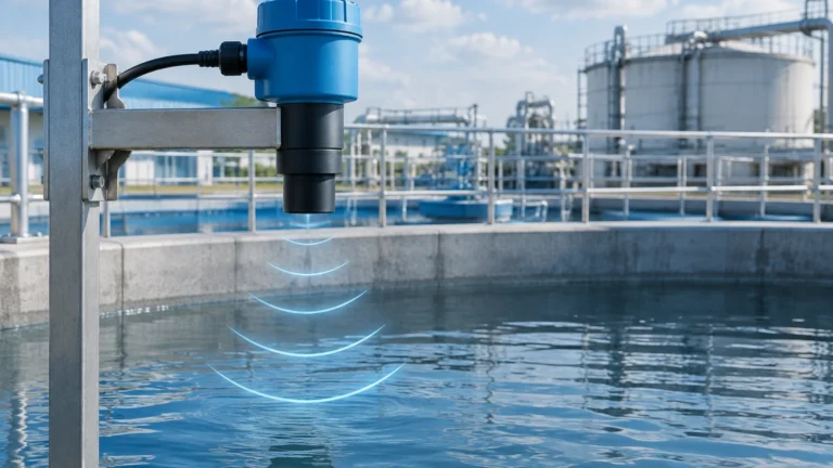
* Ambient Light: Optical sensors are sensitive to external light. In open channels or tanks, the sensor should be shielded or submerged deep enough to avoid sunlight interference.
* Bubbles: Micro-bubbles scatter light similarly to particles, leading to artificially high turbidity readings. In low-turbidity applications, the use of a de-bubbling chamber or a stilling well is highly recommended.
* Wall Effects: In small-diameter pipes, the light beam may reflect off the internal pipe wall and return to the detector. Using matte-black internal coatings or ensuring a minimum clearance of 50 mm from the pipe wall can mitigate this.
Cable Management
Industrial environments often involve electromagnetic interference (EMI). Use shielded cables and ensure they are routed away from high-voltage power lines or variable frequency drives (VFDs) to prevent signal degradation.
Operational Limitations and Maintenance Requirements
While optical turbidity sensors are highly accurate, they are not "set and forget" instruments. They are subject to several physical limitations:
* Biofouling and Scaling: In water treatment, algae or mineral scales (like calcium carbonate) can grow on the optical window. This attenuates the light and causes a positive drift in readings. Many modern sensors include integrated mechanical wipers or ultrasonic cleaning systems to address this.
* Particle Size Sensitivity: Two samples with the same mass concentration of solids can produce different turbidity readings if the particle size distribution differs. Finer particles generally scatter more light per unit of mass than larger particles.
* Color Interference: Although NIR light reduces the impact of color, extremely dark liquids (like coffee or dye-heavy wastewater) can still absorb light, potentially skewing results if the sensor is not calibrated for that specific fluid.
Maintenance Schedule:
* Weekly: Visual inspection of the sensor head and manual cleaning if a wiper is not present.
* Monthly: Verification against a secondary handheld turbidimeter.
* Quarterly/Semi-Annually: Full calibration using Formazin standards or stabilized polymer beads (AMCO clear).
Integration with Level Measurement Systems
In many industrial B2B contexts, turbidity measurement is a complementary process to level measurement. In wastewater clarifiers, for instance, an optical turbidity sensor is used to monitor the quality of the effluent, while a hydrostatic or ultrasonic level transmitter monitors the overall tank level.
Advanced applications involve "interface level detection," where a sensor moves vertically through a tank to find the "sludge blanket." In this scenario, the turbidity sensor acts as the primary detector to identify the transition from clear water to dense solids. By integrating these analytical sensors with reliable level measurement hardware, plant operators can automate sludge wasting processes, thereby saving energy and chemical costs. For those designing such integrated systems, referring to the Main Page of a specialized manufacturer ensures that the chosen level and analytical instruments are compatible in terms of mounting, power requirements, and data output.
Frequently Asked Questions (FAQs)
Q: What is the difference between NTU and FNU?
A: NTU (Nephelometric Turbidity Units) typically refers to measurements made with a white light source (EPA Method 180.1), while FNU (Formazin Nephelometric Units) refers to measurements made with an infrared light source (ISO 7027). While they use the same 90-degree scattering principle, the values may differ in colored liquids.
Q: Can an optical turbidity sensor measure Total Suspended Solids (TSS)?
A: Yes, but only through correlation. Turbidity is an optical property, while TSS is a gravimetric (weight-based) measurement. To report TSS, a site-specific calibration must be performed where turbidity readings are compared against laboratory-filtered dry-weight samples.
Q: How do I handle sensors in abrasive slurries?
A: In abrasive environments, such as mining or sand washing, use sensors with sapphire windows and sacrificial wear plates. Lowering the flow velocity at the point of measurement can also extend the life of the optical surface.
Q: Is calibration with Formazin dangerous?
A: Formazin is a known carcinogen and must be handled with care, using gloves and eye protection. Many facilities are switching to stabilized synthetic standards, which are non-toxic and have a longer shelf life, though they are more expensive.
Q: How does temperature affect the sensor?
A: While the optical measurement itself is relatively stable across temperatures, the electronics and the physical properties of the liquid can change. Most industrial sensors include an internal thermistor to provide temperature-compensated data, ensuring accuracy across a range of 0°C to 50°C (32°F to 122°F).