Flow Cb
Flow Cb
In the landscape of industrial process automation, the term "flow cb" typically refers to the integration of flow control blocks or control boards within a wider level measurement system. These components are essential for converting raw distance or level data into actionable volumetric flow rates, particularly in open channel environments or partially filled pipes. For engineers and plant managers, understanding the synergy between level sensors and the flow calculation logic is paramount for achieving high-precision monitoring in water treatment, chemical processing, and industrial drainage applications.
Accurate flow measurement often begins with precise level detection. By utilizing advanced sensors such as radar or ultrasonic transmitters, a system can determine the "head" or height of a liquid as it passes through a primary flow element like a flume or weir. The flow cb then applies specific mathematical algorithms to this height data to output the instantaneous flow rate and totalized volume.
Measurement Principles: From Level to Flow
The fundamental principle underlying most flow cb systems is the relationship between the liquid level (head) and the discharge rate in an open channel. Unlike closed-pipe systems where pressure differentials or electromagnetic properties are measured, open channel flow relies on the geometry of the channel and the gravity-driven velocity of the fluid.
The Head-Flow Relationship
Before a flow cb can generate data, the physical installation must include a primary device—typically a weir (a dam-like obstruction) or a flume (a shaped constriction in the channel). Each of these structures has a known hydraulic characteristic. The general formula used by the calculation block is:
Q = C × hⁿ
Where:
* Q is the flow rate (e.g., m³/h or L/s).
* C is the discharge coefficient specific to the geometry of the flume or weir.
* h is the measured head (liquid level).
* n is an exponent that varies based on the type of device (e.g., 1.5 for rectangular weirs, 2.5 for V-notch weirs).
Sensor Technologies
To provide the "h" value to the flow cb, two primary non-contact technologies are favored:
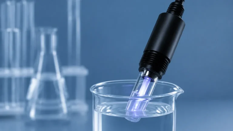
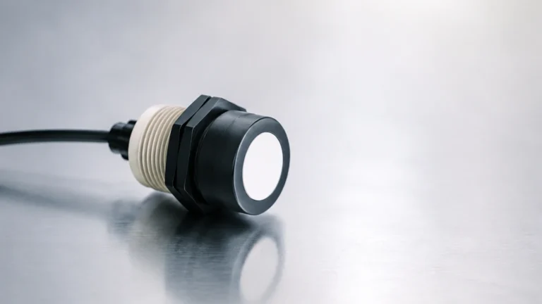
1. Ultrasonic Level Sensors: These emit high-frequency sound pulses that reflect off the liquid surface. The time-of-flight is measured to determine the distance. These are cost-effective and highly reliable for clean water applications.
2. Radar Level Meters: Utilizing high-frequency microwave signals (often 26GHz or 80GHz), radar sensors are unaffected by air temperature fluctuations, steam, or dust. They provide superior accuracy in complex chemical environments where ultrasonic signals might be attenuated.
For a comprehensive overview of available sensor technologies and their integration into control systems, engineers should refer to the Main Page of the manufacturer’s technical documentation.
Hardware Integration: Sensors and Control Blocks
A functional flow cb setup is more than just a sensor; it is a multi-component system designed to handle signal processing, data logging, and control outputs. The "CB" or control block serves as the brain of the operation.
The Control Board (CB) Architecture
In modern industrial instruments, the flow cb may be an internal circuit board within the transmitter or a separate logic block within a Programmable Logic Controller (PLC). Its primary functions include:
* Signal Linearization: Converting the non-linear relationship between level and flow into a linear output.
* Data Totalization: Keeping a running count of the total volume of liquid that has passed through the system over a specific period (e.g., daily or monthly totals).
* Communication Interfacing: Providing outputs via 4-20mA loops, RS485 (Modbus RTU), or HART protocols to send data to a centralized SCADA system.
Power and Enclosure Requirements
Industrial environments require robust hardware. Most flow cb units are housed in IP66 or IP67-rated enclosures to protect against moisture and dust. Power requirements typically range from 12-24V DC for loop-powered units to 110-220V AC for high-power integrated controllers with multiple relay outputs.
Key Evaluation Criteria for Flow CB Systems
Selecting the right flow cb configuration requires a detailed analysis of the process conditions. Failure to account for environmental variables can lead to significant measurement errors.
Media Characteristics
If the liquid is prone to foaming, ultrasonic sensors may fail as the foam absorbs the sound waves. In such cases, a radar-based flow cb system is necessary. Similarly, if the liquid is highly corrosive, the sensor face must be constructed from resistant materials like PTFE or PVDF.
Accuracy and Repeatability
In billing or environmental compliance applications, accuracy is critical. A standard flow cb system should offer an accuracy of at least ±0.5% to ±1% of the measured range. Repeatability ensures that the system provides consistent readings under identical flow conditions, which is vital for trend analysis.
Channel Geometry
The type of flume or weir installed dictates the programming of the flow cb. Common types include:
* Parshall Flumes: Ideal for large-scale water treatment.
* V-Notch Weirs: Best for low flow rates where high sensitivity is required.
* Palmer-Bowlus Flumes: Commonly used in existing sewer pipes due to their ease of installation.
Installation and Engineering Best Practices
The performance of a flow cb is heavily dependent on the physical installation of the level sensor relative to the primary flow element.
Positioning the Sensor
The sensor must be installed at a specific distance upstream from the weir or flume to avoid the "draw-down" effect. Draw-down occurs as the liquid accelerates toward the constriction, causing the surface level to drop prematurely. Typically, the sensor should be placed at a distance of 3 to 4 times the maximum head (H max) upstream.
Dead Zone Management
Every ultrasonic and radar sensor has a "dead zone" or "blocking distance" (usually 0.2m to 0.5m or 8" to 20"). The sensor must be mounted high enough so that even at the maximum possible flow level, the liquid surface does not enter this zone. If the liquid enters the dead zone, the flow cb will output an error or a fixed maximum value, leading to data loss.
Turbulence and Stilling Wells
If the flow is highly turbulent, the liquid surface will be unstable, causing the sensor readings to fluctuate. In these scenarios, a stilling well—a vertical pipe that dampens surface waves—should be used. The flow cb can then measure the level inside the well, providing a much smoother and more accurate flow calculation.

Common Risks and Mitigation Strategies
Implementing a flow cb system involves navigating several technical challenges that can compromise data integrity.
* Signal Interference: In narrow channels, false echoes from the walls can confuse the sensor. Modern radar units use "false echo suppression" software to map out these obstructions and ignore them.
* Temperature Gradients: Ultrasonic sensors rely on the speed of sound, which changes with air temperature. A flow cb using ultrasonic technology must include an integrated temperature sensor to compensate for these changes in real-time.
* Sedimentation: In wastewater applications, solids can build up behind a weir or inside a flume. This changes the hydraulic geometry and leads to over-reporting of flow. Regular maintenance and cleaning schedules are essential to mitigate this risk.
* Power Surges: Industrial sites are prone to electrical noise and surges. Ensuring the flow cb is properly grounded and equipped with surge protection prevents premature component failure.
Selection Table and Comparison
The following table provides a quick reference for choosing the appropriate technology to pair with a flow cb based on application needs.
| Feature | Ultrasonic Flow CB System | Radar Flow CB System | Hydrostatic Flow CB System |
| :— | :— | :— | :— |
| Best Use Case | Clean water, open channels | Chemical tanks, foaming liquids | Deep wells, pressurized tanks |
| Accuracy | ±0.25% to ±0.5% | ±1mm to ±3mm | ±0.1% to ±0.5% |
| Cost | Moderate | Higher | Economical |
| Maintenance | Low (Non-contact) | Very Low (Non-contact) | Moderate (Contact-based) |
| Environmental Limits | Sensitive to wind/temp | Unaffected by vapors/temp | Sensitive to density changes |
| Installation | Top-mounted | Top-mounted | Submerged or side-mounted |
Frequently Asked Questions (FAQ)
Q: Can a flow cb be used for closed pipe flow?
A: While primarily designed for open channels, some flow cb logic can be applied to partially filled pipes if the slope and pipe diameter are known (using the Manning Equation). However, for full pipes, electromagnetic or ultrasonic transit-time flowmeters are generally preferred.
Q: How often should the flow cb be calibrated?
A: Calibration frequency depends on local regulations and the criticality of the data. For environmental discharge compliance, annual or semi-annual verification against a manual measurement is standard practice.
Q: What is the maximum distance between the sensor and the flow cb?
A: If the flow cb is integrated into the sensor head, the limit is the communication cable length (up to 1000m for RS485). If using a 4-20mA analog signal, distances of 300-500m are common, provided high-quality shielded cabling is used to prevent signal degradation.
Q: Does the flow cb account for different liquid densities?
A: Non-contact methods (radar/ultrasonic) measure the surface level regardless of density. However, if a hydrostatic pressure sensor is used to provide data to the flow cb, the specific gravity of the liquid must be programmed into the calculation block to ensure accuracy.
Q: Can one flow cb monitor multiple channels?
A: Some advanced multi-channel controllers can accept inputs from two or more sensors and process separate flow calculations simultaneously. This is often used in facilities with parallel treatment trains.
By carefully considering the relationship between hydraulic structures and electronic control blocks, engineers can implement a flow cb system that provides reliable, long-term data. Whether the application involves monitoring municipal wastewater or managing chemical plant effluent, the combination of robust Welk sensors and intelligent calculation logic ensures process transparency and regulatory compliance.