Oil Gas Separation Solutions
Oil Gas Separation Solutions
In the upstream and midstream oil and gas sectors, the efficient separation of wellhead fluids into their constituent components—oil, gas, and water—is a fundamental process. Effective oil gas separation solutions are critical for meeting product specifications, protecting downstream equipment, and ensuring environmental compliance. At the heart of these solutions lies the precise measurement and control of liquid levels and interfaces within separation vessels.
Separation processes typically occur in pressurized vessels known as separators, which can be horizontal or vertical. These vessels use gravity, centrifugal force, and internal components like mist extractors and baffles to isolate phases. However, without accurate instrumentation to monitor the accumulation of these phases, the separation process cannot be automated or optimized. This article explores the technologies, selection criteria, and engineering considerations for level measurement within modern oil gas separation solutions.
The Role of Level Measurement in Separation
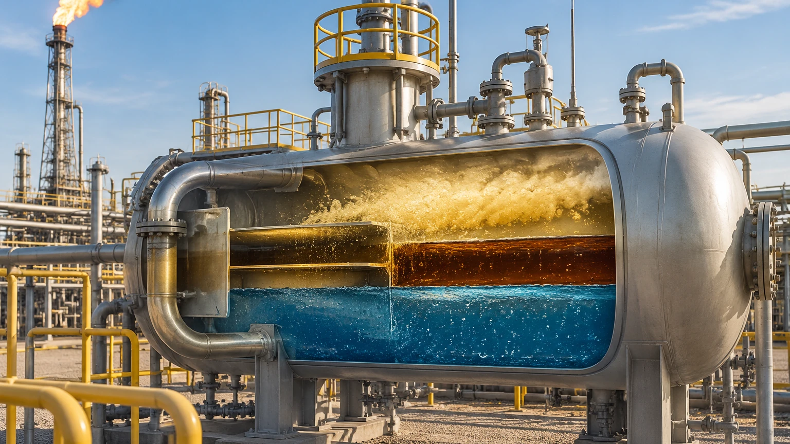
In a standard three-phase separator, the vessel contains a gas zone at the top, an oil layer in the middle, and a water layer at the bottom. To manage this effectively, operators must monitor two distinct levels:
1. Total Liquid Level: The boundary between the gas and the oil.
2. Interface Level: The boundary between the oil and the produced water.
Maintaining these levels within specific setpoints is vital for preventing "gas carry-under" (gas escaping through the liquid outlets) and "liquid carry-over" (liquid entering the gas stream). Furthermore, accurate interface control ensures that the oil is sufficiently dehydrated and the water is clean enough for disposal or reinjection.
Measurement Principles for Separation Vessels
Selecting the right instrumentation requires an understanding of the physical principles governing different sensor types. For a comprehensive overview of available technologies, engineers often consult the Main Page of specialized instrument manufacturers like Welk.
Guided Wave Radar (GWR)
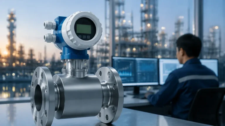
Guided Wave Radar operates on the principle of Time Domain Reflectometry (TDR). A low-energy microwave pulse is sent down a probe (waveguide). When the pulse hits a medium with a different dielectric constant ($ε_r$), a portion of the energy is reflected back to the transmitter.
In oil gas separation, GWR is particularly effective for interface measurement. Because oil has a low dielectric constant ($ε_r ≈ 2.0$) and water has a high dielectric constant ($ε_r ≈ 80$), the pulse passes through the oil layer and reflects off the water layer. This allows the sensor to track both the upper total level and the lower interface level simultaneously.
Non-Contact Radar
Non-contact radar transmitters emit microwave signals through the air or gas space. This technology is ideal for measuring the total liquid level in high-pressure separators where the probe of a GWR might be subject to mechanical stress or paraffin buildup. It is less sensitive to changes in gas composition and pressure than ultrasonic methods.
Magnetic Level Gauges (MLG)
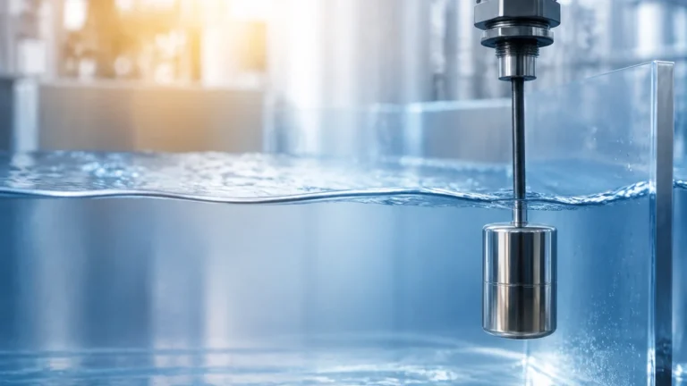
MLGs consist of a bypass chamber mounted to the side of the separator. A float containing a permanent magnet moves with the liquid level, flipping magnetized flags on an external scale to provide a visual indication. For remote monitoring, a magnetostrictive transmitter can be attached to the chamber. These are highly valued for their robustness and the fact that they do not require power for visual local indication.
Hydrostatic Pressure
Hydrostatic transmitters measure the pressure exerted by the liquid column. In a pressurized separator, a differential pressure (DP) approach is required to subtract the gas headspace pressure. While cost-effective, hydrostatic measurement is sensitive to changes in fluid density, which can occur if the temperature or the crude oil composition fluctuates.
Comparison of Level Technologies for Separation
The following table provides a comparison of common technologies used within oil gas separation solutions.
| Technology | Accuracy | Pressure Range | Interface Measurement | Maintenance Needs |
| :— | :— | :— | :— | :— |
| Guided Wave Radar | ±2 mm | Up to 400 bar (40 MPa) | Excellent | Low (no moving parts) |
| Non-Contact Radar | ±1 mm | Up to 160 bar (16 MPa) | Not recommended | Very Low |
| Magnetic Gauge | ±5 mm | Up to 320 bar (32 MPa) | Good (requires float sizing) | Medium (float cleaning) |
| Hydrostatic (DP) | ±0.1% Span | High | Calculated | Medium (calibration) |
| Ultrasonic | ±5 mm | Atmospheric only | No | Low |
Engineering Challenges: Emulsions and Rag Layers
One of the most significant hurdles in oil gas separation solutions is the formation of a "rag layer" or emulsion between the oil and water. This is a mixture of oil, water, and solids (like sand or paraffin) that does not separate cleanly.
* Impact on GWR: A thick, stable emulsion may scatter the radar signal, leading to a "lost signal" or an inaccurate interface reading. Using a coaxial probe can help concentrate the signal, but it may be prone to clogging if the crude is heavy.
* Impact on Magnetic Gauges: If the emulsion density is close to the oil or water density, the float may sit at an unpredictable depth within the rag layer.
* Solution: In these cases, multiphase profiling or capacitance-based probes may be used as supplementary technologies, though GWR remains the industry standard for most separators.
Installation Considerations for Separators
Proper installation is as critical as technology selection. Engineers must consider the following to ensure the longevity and accuracy of the measurement system:
1. Nozzle Location: Level instruments should be installed away from the inlet flow to avoid turbulence and foam. If the inlet is high-velocity, internal baffles or stilling wells are necessary.
2. Stilling Wells: For both radar and float-based systems, a stilling well (a vertical pipe within the vessel) can provide a calm surface for measurement, protecting the sensor from the agitation caused by gas breakout.
3. Vapor Space Complications: In high-pressure gas separators, the gas density can increase significantly, slowing down the speed of radar pulses. High-end radar transmitters include gas phase compensation (using a reference reflection) to maintain accuracy.
4. Material Compatibility: Components in contact with the process fluid must resist H2S (sour gas) and CO2 corrosion. Standard materials include 316L Stainless Steel, with Hastelloy or Monel used for more aggressive environments.
Practical Selection Criteria
When specifying instruments for oil gas separation solutions, the following parameters must be confirmed:
* Operating Pressure and Temperature: Ensure the instrument housing and seals (such as Viton or Kalrez) can withstand the maximum design conditions. For example, high-pressure separators often operate above 100 bar (1450 psi).
* Fluid Properties: Dielectric constants of the oil and water, as well as the specific gravity (SG) of each phase. A float for a magnetic gauge must be weighted specifically for the interface SG.
* Vessel Geometry: The height of the vessel determines the probe length for GWR or the chamber length for an MLG. For horizontal separators, the measurement range is usually smaller but requires higher precision.
* Certifications: Most oil and gas sites require ATEX, IECEx, or SIL2/3 safety certifications for electronic instruments.
Maintenance and Troubleshooting
Even the most advanced oil gas separation solutions require periodic maintenance. Common issues include:
* Paraffin/Wax Buildup: In colder climates or with heavy crudes, paraffin can coat radar probes or jam magnetic floats. Heat tracing or specialized coatings on the probes can mitigate this.
* Scaling: Mineral deposits from produced water can interfere with sensor sensitivity. Periodic cleaning during vessel turnarounds is recommended.
* Calibration Drifts: While radar is generally drift-free, hydrostatic and capacitance sensors should be checked annually against a known reference.
Frequently Asked Questions (FAQ)
Q: Can ultrasonic sensors be used in high-pressure oil-gas separators?
A: Generally, no. Ultrasonic sensors rely on the speed of sound, which changes significantly with gas pressure, temperature, and composition. Furthermore, the high-pressure seals required for separators are difficult to implement with ultrasonic transducers. Radar is the preferred non-contact method.
Q: How do you measure the level if there is heavy foam on the oil surface?
A: Foam can absorb radar signals. Guided Wave Radar with a high-sensitivity end-of-probe algorithm or a magnetic level gauge (which ignores foam) are the best options for foamy applications.
Q: What is the benefit of a bypass chamber (external cage) for level measurement?
A: A bypass chamber allows the instrument to be isolated from the main vessel for maintenance or calibration without shutting down the process. It also acts as a natural stilling well, reducing turbulence.
Conclusion
Optimizing oil gas separation solutions requires a holistic approach that combines robust vessel design with precise level instrumentation. By understanding the dielectric properties of the fluids and the mechanical constraints of the separator, engineers can select technologies—such as those provided by Welk—that ensure reliable operation, even in the presence of emulsions, high pressures, and corrosive gases. Whether utilizing the precision of Guided Wave Radar or the reliability of Magnetic Level Gauges, the goal remains the same: clear separation and safe, efficient production.