Cpa Flow Conditioners
Cpa Flow Conditioners
In industrial fluid dynamics, the accuracy of measurement instruments is heavily dependent on the state of the fluid as it passes through the sensing point. CPA flow conditioners, originally developed by Canada Pipeline Accessories, represent a critical advancement in flow profile management. These devices are engineered to eliminate swirl and restore a fully developed flow profile in piping systems where space is limited. While flow conditioners are traditionally associated with flow meters, their role in stabilizing process conditions is equally vital for the performance of level measurement systems, particularly in dynamic industrial environments.
Understanding the Role of CPA Flow Conditioners in Process Control
Process engineers often face the challenge of "non-ideal" piping configurations. Bends, elbows, valves, and T-junctions introduce turbulence and swirl into the fluid stream. For measurement technologies—whether they are ultrasonic flow meters or high-precision level sensors in bypass chambers—this turbulence creates "noise" and inaccuracy.
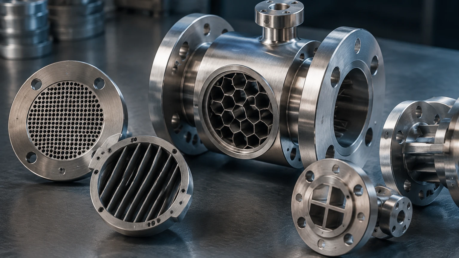
CPA flow conditioners are perforated plate devices designed to transform chaotic flow into a predictable, symmetrical velocity profile. By utilizing a specific arrangement of holes of varying diameters, these plates redistribute the kinetic energy of the fluid. This ensures that when the fluid reaches a measurement instrument, it behaves according to the theoretical models used by the instrument’s software, thereby reducing the margin of error.
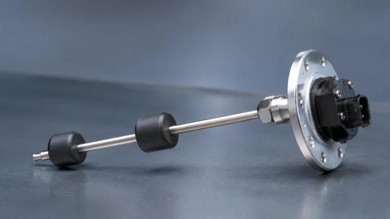
In the context of level measurement, such as those provided by Welk, flow conditioners are often utilized in the inlet piping of surge tanks or separator vessels. By stabilizing the inflow, the conditioner prevents excessive surface agitation, which allows radar and ultrasonic level meters to provide more stable and reliable readings. For a comprehensive overview of how these instruments integrate into process systems, engineers can refer to the Main Page for technical specifications on level measurement hardware.
Measurement Principles and Fluid Dynamics
The fundamental principle behind CPA flow conditioners is the management of the Reynolds number and the elimination of swirl components. Swirl is a tangential velocity component that causes the fluid to rotate as it moves downstream, often persisting for over 50 pipe diameters (50D) if left untreated.
Swirl Reduction
As fluid passes through the perforated holes of a CPA plate, the large-scale vortices are broken down into smaller, short-lived eddies. The thickness of the plate and the geometry of the holes are calculated to provide enough resistance to straighten the flow without causing an excessive pressure drop.
Profile Correction
A "fully developed" flow profile is one where the velocity is highest at the center of the pipe and tapers off toward the walls due to friction. Distortions (such as those caused by two out-of-plane elbows) create an asymmetrical profile. The CPA design uses a patented hole pattern—often featuring a large central hole surrounded by concentric rings of smaller holes—to force the fluid into the desired power-law velocity distribution.
Technical Comparison: CPA Designs vs. Alternative Solutions
Before selecting a flow conditioner, it is essential to understand how CPA designs differ from older technologies like vane-type straighteners or standard orifice plates.
| Feature | Vane-Type Straighteners | Standard Perforated Plates | CPA Flow Conditioners (e.g., 50E) |
| :— | :— | :— | :— |
| Swirl Removal | Moderate | Low | High |
| Profile Correction | Minimal | Moderate | Excellent |
| Pressure Loss | Low | High | Moderate |
| Installation Length | Long (up to 20D) | Moderate | Short (typically 2D-5D) |
| Fouling Risk | High (debris traps) | Moderate | Low (self-cleaning geometry) |
| Application | Large diameter water pipes | General process | High-precision gas/liquid custody transfer |
Selection Criteria for Industrial Applications
Selecting the correct CPA flow conditioner requires an analysis of the specific process parameters. Engineers must balance the need for flow conditioning against the allowable pressure loss in the system.
1. Fluid State: Is the medium a gas, liquid, or multi-phase? CPA conditioners like the 50E are highly effective for high-pressure natural gas, while other variants may be optimized for liquid hydrocarbons or water treatment.
2. Pipe Schedule: The internal diameter (ID) of the pipe must be precisely matched. A conditioner designed for Schedule 40 pipe will not seat correctly or perform optimally in a Schedule 80 pipe.
3. Reynolds Number (Re): Most CPA conditioners are designed for turbulent flow regimes (Re > 4,000). In laminar flow, the effectiveness of perforated plates is significantly reduced.
4. Pressure Drop (Delta P): Every conditioner introduces a permanent pressure loss. This must be calculated to ensure it does not cavitation in liquid lines or drop the pressure below the required threshold for downstream equipment.
5. Material Compatibility: Standard units are often 304 or 316 stainless steel, but for corrosive chemical applications, exotic alloys or specialized coatings may be required.
Installation Guidelines and Best Practices
The performance of a flow conditioner is as much about its placement as its design. Even the best CPA plate will fail to provide a developed profile if installed too close to a downstream disturbance.
Upstream and Downstream Distances
Industry standards (such as AGA 9 or ISO 5167) provide specific guidance. Generally, a CPA flow conditioner is installed between 5D and 10D upstream of the measurement device. The distance from the preceding disturbance (like an elbow) to the conditioner should typically be at least 3D to 5D to allow the turbulence to reach the plate uniformly.
Orientation and Centering
For perforated plates, concentricity is vital. If the plate is offset from the pipe center by even a few millimeters, it can introduce a new asymmetry into the flow. Most CPA units are designed to be pinned or flanged in a way that ensures automatic centering. In horizontal liquid lines, care must be taken to ensure that the hole pattern does not promote the accumulation of sediment at the bottom of the pipe or gas pockets at the top.
Maintenance and Inspection
While CPA flow conditioners have no moving parts, they are subject to erosion and fouling. In steam applications or abrasive slurry lines, the edges of the holes can round off over time, which changes the discharge coefficient and reduces the effectiveness of the profile correction. Annual visual inspections or differential pressure monitoring are recommended.
Limitations and Operational Constraints
Despite their versatility, CPA flow conditioners are not a universal solution for every piping problem.
* Pressure Loss: In low-pressure gravity systems, the 0.5 to 1.5 bar (approx. 7-22 psi) pressure drop across a conditioner may be unacceptable.
* Slurry and High-Solids Fluids: In water treatment or mining applications where the fluid contains large solids or fibrous material, perforated plates can act as a filter, leading to rapid clogging.
* Cost: High-performance flow conditioners are precision-machined components. For non-critical applications where high accuracy is not required, the investment may not be justified compared to simply increasing the length of straight pipe run.
Integration with Level Measurement Systems
While the primary market for CPA flow conditioners is the flow metering industry, their application in level control is an emerging best practice in complex plant architectures. For example, in a high-pressure separator, the incoming fluid often enters at high velocity. Without conditioning, this creates a "plume" or standing wave on the liquid surface.
If a radar level transmitter is positioned near this inlet, the turbulence can cause the signal to scatter, leading to "lost echo" errors. By installing a flow conditioner or a diffuser based on CPA principles at the inlet, the fluid enters the vessel more calmly. This allows the level measurement instruments to track the true liquid surface accurately, ensuring safety and process efficiency. For detailed information on selecting level sensors that perform well in turbulent environments, visit the Main Page.
Frequently Asked Questions (FAQ)
Q: Can a CPA flow conditioner replace straight pipe run requirements entirely?
A: No, but it significantly reduces them. For example, an ultrasonic meter that requires 20D of straight pipe might only require 5D of straight pipe if a CPA conditioner is used.
Q: What is the typical pressure drop across a CPA 50E?
A: The pressure loss coefficient (K-factor) for a standard CPA 50E is approximately 2.0 to 2.5. The actual pressure drop in kPa or bar depends on the fluid density and velocity.
Q: Are CPA flow conditioners bi-directional?
A: Most CPA designs are optimized for uni-directional flow. While they will provide some conditioning in reverse flow, the hole chamfers and profile-shaping characteristics are usually engineered for a specific flow direction.
Q: Do they require special gaskets?
A: They are typically designed to fit between standard ANSI or DIN flanges. However, the thickness of the plate must be accounted for in the piping layout to ensure proper bolt tension and gasket seating.
Conclusion
CPA flow conditioners are essential tools for modern process engineering, providing a compact and effective means of ensuring fluid stability. By understanding the principles of profile correction and swirl reduction, engineers can significantly improve the reliability of their measurement systems. Whether the goal is custody transfer of natural gas or the stable level control of a chemical reactor, the integration of flow conditioning technology is a proven method for achieving high-precision results in challenging piping environments.