Oil & Gas Instrumentation
Oil & Gas Instrumentation
In the demanding environment of the oil and gas industry, precision and reliability are not merely performance metrics but essential requirements for safety and operational continuity. Oil & gas instrumentation encompasses a wide array of sensors and transmitters designed to monitor pressure, temperature, flow, and level. Among these, level measurement presents unique challenges due to the volatile, corrosive, and high-pressure nature of the media involved. Selecting the correct technology requires a deep understanding of the physical principles governing each instrument and the specific constraints of the process environment.
Core Measurement Principles in Level Instrumentation
Before selecting a device for a specific application, it is critical to understand how different technologies interact with the process media. In the context of oil & gas instrumentation, level measurement generally falls into two categories: continuous measurement and point level detection.
Radar Level Measurement (ToF Principle)
Radar transmitters operate on the Time-of-Flight (ToF) principle. The device emits high-frequency electromagnetic waves (typically in the 26 GHz or 80 GHz range) that travel at the speed of light. When these waves hit the surface of the liquid, they are reflected back to the sensor. The distance is calculated based on the time interval between emission and reception.
* Non-Contact Radar: Ideal for corrosive or viscous fluids as the sensor does not touch the media. It is highly effective in storage tanks where the dielectric constant of the oil is stable.
* Guided Wave Radar (GWR): Uses a physical probe (cable or rod) to guide the signal. This is particularly effective for low dielectric media or applications with heavy foam and turbulence, as the concentrated signal provides a stronger return reflection.
Ultrasonic Level Measurement
Ultrasonic sensors emit mechanical sound pulses. Like radar, they use the ToF principle, but they rely on the reflection of sound waves off the surface. Because sound requires a medium to travel, its speed is affected by air temperature, pressure, and gas composition. While cost-effective, ultrasonic sensors are often limited in oil and gas applications involving high pressure or heavy vapor layers, which can attenuate the sound signal.
Hydrostatic Pressure Measurement
This principle relies on the relationship between the height of a liquid column and the pressure it exerts at the base. The formula $P = \rho \cdot g \cdot h$ (where $P$ is pressure, $\rho$ is density, $g$ is gravity, and $h$ is height) allows the transmitter to calculate the level. In the oil & gas sector, this is commonly used in vented tanks or, when paired with a second pressure sensor for vapor space compensation, in pressurized vessels.
Magnetic Level Gauges
Magnetic level gauges utilize a float containing a high-intensity magnet. As the liquid level rises and falls, the float moves within a bypass chamber. This movement flips magnetic flags on an external scale and can be coupled with a reed chain or magnetostrictive transmitter for remote signal output. This provides both a local visual indication and a digital signal for the control room.
Critical Evaluation Criteria for Technology Selection
Choosing the right oil & gas instrumentation involves balancing technical specifications with environmental realities. Engineers must evaluate the following criteria:
1. Process Temperature and Pressure: Offshore separators or high-pressure distillation columns require instruments capable of withstanding pressures exceeding 100 bar (1450 PSI) and temperatures above 200°C (392°F).
2. Media Characteristics: The dielectric constant ($ε_r$) is the most critical factor for radar. Hydrocarbons generally have low dielectric constants (1.8 to 2.5), requiring high-sensitivity radar or guided wave technology. Viscosity and the tendency for paraffin or wax buildup must also be considered for contact-type probes.
3. Hazardous Area Requirements: Most oil and gas sites are classified as Zone 0, 1, or 2. Instruments must carry appropriate ATEX, IECEx, or North American explosion-proof/intrinsically safe certifications.
4. Accuracy and Repeatability: For custody transfer (fiscal metering), high-accuracy radar gauges (within ±0.5 mm) are required. For process control in a separator, ±5 mm may be sufficient.
Practical Selection Table for Oil & Gas Applications
| Technology | Accuracy | Max Pressure (Typical) | Media Suitability | Best Application |
| :— | :— | :— | :— | :— |
| 80 GHz Radar | ±1 mm | Up to 160 bar | Crude, Refined Products | Large storage tanks, narrow nozzles |
| Guided Wave Radar | ±2 mm | Up to 400 bar | LPG, LNG, Interface | Separators, bypass chambers |
| Ultrasonic | ±0.25% FS | Up to 3 bar | Produced water, mud pits | Open sumps, chemical storage |
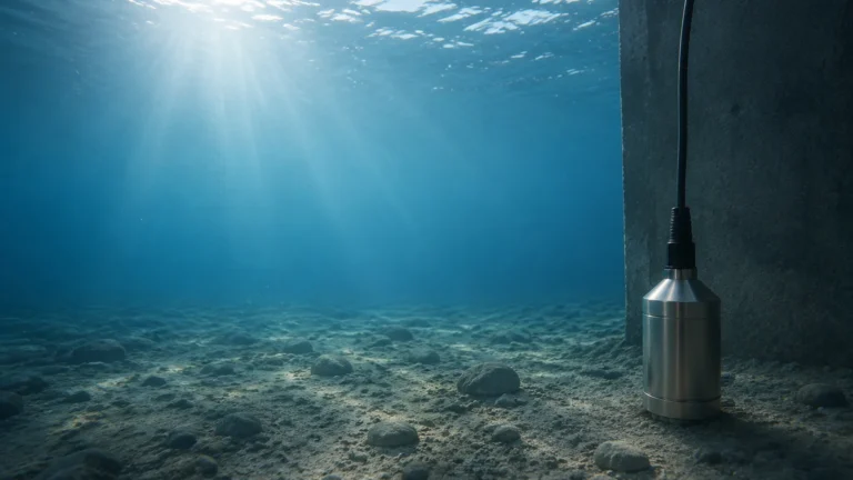
| Hydrostatic | ±0.1% FS | Dependent on sensor | Slop oil, water tanks | Submersible or flange-mounted tanks |
| Magnetic Gauge | ±5 mm | Up to 250 bar | All liquids | Visual monitoring on vessels |
Installation and Maintenance Considerations
Proper installation is as important as the technology itself. Even the most advanced oil & gas instrumentation will fail if environmental factors are ignored.
* Nozzle Geometry: For non-contact radar, the nozzle height and diameter must be considered to avoid internal reflections (parasitic echoes). 80 GHz radar is more forgiving due to its narrow beam angle.
* Stilling Wells: In tanks with heavy turbulence or internal obstructions like heating coils, installing the level sensor inside a stilling well or bypass pipe can stabilize the surface and improve signal reliability.
* Orientation: Hydrostatic transmitters should be mounted where sediment is unlikely to settle on the diaphragm. For magnetic gauges, ensuring the chamber is perfectly vertical is essential for the free movement of the float.
* Vapor Space Management: In high-pressure gas applications, the change in the composition of the vapor space can change the speed of sound (for ultrasonic) or the dielectric constant (for radar). Compensation techniques or choosing GWR can mitigate these errors.

Common Risks and Limitations
In the field, several factors can compromise the performance of oil & gas instrumentation:
* Foam and Emulsions: In oil-water separators, foam can absorb radar and ultrasonic signals. Guided wave radar is typically the best solution for tracking the true liquid level through foam.
* Paraffin and Scale Buoyancy: In crude oil applications, paraffin wax can build up on probes or floats. This increases the weight of floats or causes signal loss in GWR. Regular cleaning or the use of specialized coatings is necessary.
* Gas Phase Compensation: At high pressures, the gas phase (like high-pressure steam or methane) can slow down radar signals. Without compensation, this can lead to a measurement error of several percentage points.
Frequently Asked Questions (FAQs)
Q: Why is 80 GHz radar preferred over 26 GHz in many modern oil and gas projects?
A: 80 GHz radar offers a much narrower beam angle (as small as 3 degrees). This allows the signal to avoid internal tank obstructions like ladders or agitators and enables installation in smaller nozzles, reducing the risk of false echoes.
Q: Can hydrostatic transmitters be used for interface measurement?
A: Only if the total level is constant or if multiple sensors are used. For dynamic interface measurement (e.g., the line between oil and water in a separator), Guided Wave Radar is generally more reliable as it detects the change in dielectric constant at the interface layer.
Q: How does the dielectric constant affect radar selection?
A: If the dielectric constant of the oil is very low (below 1.5), the reflected signal is weak. In these cases, a Guided Wave Radar or a non-contact radar with a larger antenna/higher frequency is required to ensure a sufficient signal-to-noise ratio.
Engineering Support and Solutions
Selecting the appropriate instrumentation requires a balance between initial capital expenditure and long-term maintenance costs. For complex applications involving high temperatures, cryogenic storage (LNG), or high-pressure separators, consulting with a manufacturer that offers a diverse range of technologies is essential. You can Review product options and application support at our Main Page to find detailed specifications and engineering drawings for your specific project requirements.
Reliable oil & gas instrumentation is the foundation of process automation. By understanding the physics of measurement and the specific demands of the hydrocarbon environment, engineers can ensure both the safety of their personnel and the efficiency of their operations.