Vector Automation
Vector Automation
In the landscape of modern industrial processing, vector automation represents the convergence of high-precision measurement and intelligent control logic. For engineers and plant managers, transition from manual monitoring to a fully automated vector-based system is no longer a luxury but a necessity for maintaining operational efficiency, safety, and cost-effectiveness. This guide explores how advanced level measurement technologies serve as the critical data input for vector automation systems, ensuring that every process variable is accounted for with mathematical precision.
Vector automation in process control refers to the systematic management of physical variables—such as fluid level, flow rate, and pressure—treated as dynamic vectors within a control loop. Unlike simple on/off controls, vector-based automation considers the magnitude and the rate of change, allowing for predictive adjustments and smoother industrial workflows. At the heart of this system lies the level meter, a device that provides the primary data vector required for the automation software to make informed decisions.
Understanding the Principles of Level Measurement in Automated Systems
Before implementing a vector automation strategy, it is essential to understand the physical principles that govern level measurement. Different technologies offer varying degrees of accuracy and compatibility with automated control systems.
Radar Level Measurement (Time of Flight)
Radar level meters utilize electromagnetic waves, typically in the 26GHz or 80GHz frequency range. The device emits a signal that travels to the surface of the medium and reflects back. By measuring the time of flight (ToF), the system calculates the distance with extreme precision. In the context of vector automation, radar is highly valued because it is non-contact and unaffected by changes in temperature, pressure, or vapor space composition. High-frequency 80GHz radar, in particular, offers a narrow beam angle, which minimizes interference from internal tank structures, providing a "clean" data vector for the PLC (Programmable Logic Controller).
Ultrasonic Level Sensing
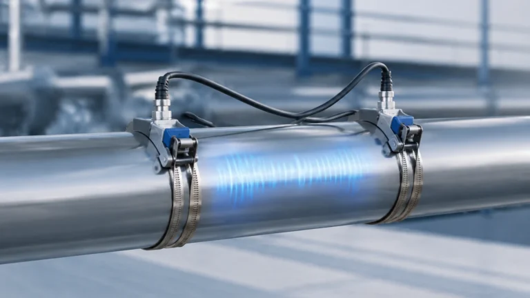
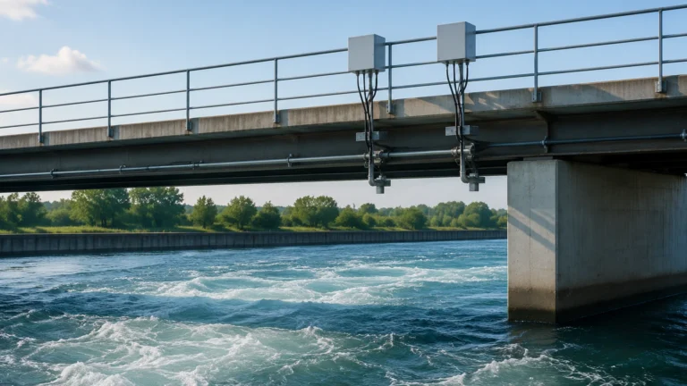
Ultrasonic sensors function similarly to radar but use sound waves instead of electromagnetic waves. The sensor emits an ultrasonic pulse that reflects off the liquid surface. While cost-effective, ultrasonic measurement is sensitive to air temperature and turbulence. For automation purposes, these sensors often include integrated temperature compensation to ensure the data vector remains accurate despite environmental fluctuations. They are ideal for open-channel flow and standard water treatment applications.
Hydrostatic Pressure Measurement
Hydrostatic level transmitters measure the pressure exerted by a liquid column. The principle is based on the formula $P = \rho gh$, where $P$ is pressure, $\rho$ is the density of the fluid, $g$ is gravity, and $h$ is the height of the liquid. This technology provides a continuous analog or digital signal that is easily integrated into vector automation loops. It is particularly effective in vented tanks where the fluid density remains relatively constant.
The Integration of Vector Automation in Process Control
Integrating level measurement into a vector automation framework requires more than just a sensor; it requires a robust communication protocol. Modern instruments from manufacturers like Welk utilize various output signals to feed data into the automation architecture.
1. 4-20mA Analog Signals: The traditional standard, where the current represents the level percentage. While reliable, it is limited to a single variable.
2. HART Protocol: This allows digital information to be superimposed on the 4-20mA signal, providing diagnostic data and multiple process variables (e.g., level and temperature) to the automation system.
3. Modbus and Profibus: These digital communication protocols enable high-speed data transfer and are essential for complex vector automation setups where dozens of sensors must be polled simultaneously.
By treating the level data as a dynamic vector, the automation system can calculate the volumetric flow rate and the time remaining until a tank reaches a high-level setpoint. This predictive capability is the hallmark of sophisticated vector automation, allowing for the synchronization of pumps and valves to prevent overflows or dry-run conditions.
Selection Criteria for Automation-Ready Level Instruments
Choosing the right instrument is the most critical step in designing a vector automation system. Engineers must evaluate the following criteria to ensure the hardware can support the desired level of automation:
* Accuracy and Repeatability: For vector control, repeatability is often more important than absolute accuracy. The system needs consistent data to maintain stable PID (Proportional-Integral-Derivative) loops.
* Response Time: In fast-filling applications, the sensor must update its output quickly enough for the automation logic to react. Radar sensors typically offer faster refresh rates than hydrostatic sensors.
* Media Compatibility: The chemical properties of the liquid (corrosiveness, viscosity, dielectric constant) dictate the sensor material and technology. For example, a low dielectric constant liquid might require a guided wave radar rather than a standard non-contact radar.
* Environmental Conditions: High temperatures (above 150°C) or high pressures (above 40 bar) require specialized sensor housings and seals.
For a comprehensive overview of available technologies and detailed technical specifications, engineers should consult the Main Page of the industrial instrument catalog.
Practical Selection Table for Industrial Level Sensors
The following table provides a quick reference for selecting level measurement technologies based on common industrial requirements for vector automation.
| Technology | Accuracy | Ideal Media | Max Range (m) | Automation Compatibility | Limitations |
| :— | :— | :— | :— | :— | :— |
| 80GHz Radar | ±1 mm | Liquids/Solids | 120m | Excellent (Digital/Analog) | High initial cost |
| Ultrasonic | ±0.25% | Water/Waste | 15m | High (Analog) | Affected by foam/vapor |
| Hydrostatic | ±0.1% | Clean Liquids | 200m | High (4-20mA) | Density dependent |
| Magnetic Gauge | ±5 mm | Corrosive Liquids | 6m | Moderate (Requires Switch) | Moving parts |
| Guided Wave Radar | ±2 mm | Low Dielectric | 30m | Excellent (HART) | Contacting method |

Installation Best Practices for Data Integrity
In vector automation, the quality of the control is only as good as the quality of the input data. Improper installation can introduce "noise" into the data vector, leading to erratic system behavior. Follow these guidelines to ensure optimal performance:
1. Avoid Obstructions
For radar and ultrasonic sensors, ensure the signal path is clear of ladders, agitators, or inlet pipes. Even a small obstruction can cause false echoes. Modern sensors feature "false echo suppression," but physical clearance is always preferred.
2. Positioning
The sensor should typically be installed at 1/2 to 1/3 of the tank radius from the wall. Installing too close to the wall can cause signal interference, while installing directly in the center can lead to multiple reflections in domed-top tanks.
3. Stilling Wells
In applications with heavy turbulence or foam, consider using a stilling well or a bypass chamber. This provides a calm surface for the sensor to measure, ensuring a stable data vector for the automation system.
4. Cable Shielding and Grounding
To prevent electromagnetic interference (EMI) from variable frequency drives (VFDs) and motors, use shielded cables and ensure proper grounding. This is vital for maintaining the integrity of the 4-20mA or digital communication signal.
Limitations and Common Risks in Automated Level Systems
While vector automation significantly improves process reliability, engineers must be aware of potential limitations and risks:
* Signal Loss: In non-contact sensors, extreme foam or heavy dust can absorb the signal, leading to a "loss of echo." Automation logic must include a "fail-safe" state (e.g., hold last value or go to 100%) to handle these events.
* Density Fluctuations: Hydrostatic sensors rely on a constant fluid density. If the temperature changes significantly or if different fluids are mixed, the level reading will drift. In these cases, a redundant radar sensor is often used for cross-verification.
* Build-up and Coating: In sticky or viscous applications, material build-up on the sensor face can degrade performance. Choosing a sensor with a flush-mounted antenna or a self-cleaning function is necessary for long-term automation reliability.
* Cybersecurity: As vector automation systems become more connected, the risk of external interference increases. Ensure that the communication protocols (like Modbus TCP) are implemented within a secure industrial network.
Frequently Asked Questions (FAQs)
Q: Can vector automation be applied to solids measurement?
A: Yes. High-frequency radar is particularly effective for solids. The automation system can use the level data to calculate the volume of silos and manage bulk material handling equipment.
Q: What is the difference between a level switch and a level transmitter in automation?
A: A level switch provides a point-level signal (on/off), which is used for emergency high/low alarms. A level transmitter provides continuous data, which is required for the dynamic control loops used in vector automation.
Q: How do I handle measurement in tanks with internal agitators?
A: Use a radar level meter with a narrow beam angle and enable the "false echo suppression" or "masking" feature in the software. This allows the system to ignore the signal reflections from the moving blades.
Q: Is it necessary to recalibrate sensors frequently in an automated system?
A: Modern digital sensors like those from Welk are designed for long-term stability. However, an annual verification is recommended to ensure the data vector remains within the required tolerance for the automation logic.
Conclusion
Vector automation is the future of industrial process management, providing the precision and predictability required in today's competitive market. By understanding the underlying measurement principles—whether radar, ultrasonic, or hydrostatic—and adhering to strict installation and selection criteria, organizations can build robust systems that minimize waste and maximize safety. The integration of reliable hardware with intelligent control software creates a seamless flow of data, transforming simple level readings into powerful vectors for industrial success. For those looking to upgrade their current infrastructure, exploring a wide range of automation-ready instruments is the first step toward a more efficient, automated future.