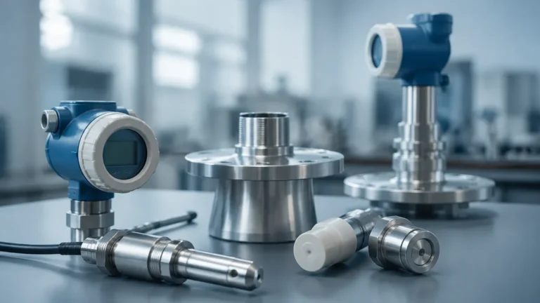
Custom Fluid Sensing Application
Custom Fluid Sensing Application
In modern industrial processing, the ability to accurately monitor liquid levels is fundamental to operational safety, efficiency, and inventory management. While standard sensors suffice for many generic storage tasks, complex environments—characterized by extreme temperatures, corrosive chemicals, high pressures, or turbulent surfaces—require a specialized approach. A custom fluid sensing application involves the strategic selection and modification of measurement technologies to meet the unique physical and chemical demands of a specific process.
Engineering a reliable solution starts with a deep understanding of the underlying measurement physics. By matching the right sensing principle to the fluid characteristics, engineers can mitigate risks such as sensor fouling, signal loss, or mechanical failure. This guide examines the primary technologies used in custom fluid sensing and provides a framework for selecting the optimal instrument for challenging industrial environments.
Core Measurement Principles
Before specifying hardware for a custom fluid sensing application, it is essential to understand how different technologies interact with the medium and the vessel.
Radar Level Measurement (Non-Contact and Guided)
Radar technology utilizes electromagnetic waves to determine the distance to a product surface. In non-contact radar, the sensor emits a high-frequency signal (typically 26GHz or 80GHz) that reflects off the liquid surface and returns to the antenna. The time-of-flight or frequency shift is used to calculate the level.
Guided Wave Radar (GWR) functions similarly but directs the signal along a physical probe or cable. This is particularly effective in a custom fluid sensing application where low dielectric constants or heavy foam might dissipate a non-contact signal. Radar is generally immune to changes in density, pressure, and temperature, making it a versatile choice for hazardous or high-precision environments.
Ultrasonic Level Sensing
Ultrasonic sensors emit high-frequency sound waves that bounce off the liquid surface. The sensor measures the time interval between the emission and the return of the echo. Because sound speed is influenced by air temperature, these sensors typically include integrated temperature compensation. Ultrasonic technology is cost-effective and ideal for water treatment or open-channel flow, though it is limited in vacuum conditions or environments with heavy vapor, as sound requires a medium to travel through.
Hydrostatic Pressure Measurement
Hydrostatic level sensing relies on the principle that the pressure at the bottom of a vessel is directly proportional to the height of the liquid column above it, multiplied by the fluid's density. For a custom fluid sensing application involving deep wells or vented tanks, submersible or flange-mounted pressure transmitters provide a robust solution. However, if the fluid density fluctuates due to temperature changes or mixing, the system must be calibrated or compensated to maintain accuracy.
Magnetic Level Gauges
Magnetic level gauges utilize a bypass chamber mounted to the side of a vessel. Inside the chamber, a float containing a permanent magnet moves with the liquid level. Outside the chamber, a visual indicator or a reed-switch transmitter tracks the magnet's position. This provides a clear visual reference and a redundant electronic signal, which is highly valued in high-pressure boiler or oil-gas separator applications.
Engineering the Custom Fluid Sensing Application
When standard catalog items do not meet process requirements, customization becomes necessary. This may involve altering the physical construction of the sensor or the signal processing logic.
Material Compatibility and Coatings
In chemical processing, sensors are often exposed to aggressive acids or bases. A custom fluid sensing application might require wetted parts made from specialized alloys like Hastelloy C-276 or coated with fluoropolymers such as PTFE, PFA, or PVDF. These materials ensure the longevity of the instrument and prevent process contamination.
Temperature and Pressure Extremes
Standard electronics are often rated for temperatures up to 80°C (176°F). For applications involving molten salts, cryogenic liquids, or high-pressure steam, custom solutions utilize remote electronics, cooling fins, or thermal isolators. High-pressure applications (exceeding 100 bar / 1450 psi) require reinforced process connections and specialized seal designs, such as Kalrez O-rings or ceramic-to-metal seals.
Signal Integration and Automation
Customization also extends to how data is retrieved. While 4-20mA HART is the industry standard, many modern facilities require integration with Modbus RTU, Foundation Fieldbus, or Profibus. For remote sites, battery-powered sensors with wireless transmission (LoRaWAN or NB-IoT) are often integrated into the custom fluid sensing application to reduce infrastructure costs.
Practical Selection Table
The following table summarizes the suitability of different technologies across common industrial parameters. For a more comprehensive review of hardware options, engineers can visit the Main Page to review product options and application support.
| Parameter | Radar (80GHz) | Ultrasonic | Hydrostatic | Magnetic Gauge |
| :— | :— | :— | :— | :— |
| Max Range | Up to 120m (393 ft) | Up to 15m (49 ft) | Up to 200m (656 ft) | Up to 6m (20 ft) |
| Accuracy | ±1mm to ±2mm | ±0.25% of range | ±0.1% to ±0.5% FS | ±5mm to ±10mm |
| Pressure Limit | 160 bar (2320 psi) | 3 bar (43 psi) | 40 bar (580 psi) | 200 bar (2900 psi) |
| Temp. Limit | 450°C (842°F) | 80°C (176°F) | 100°C (212°F) | 400°C (752°F) |
| Foam Resistance | Excellent (FMCW) | Poor | Excellent | Excellent |
| Density Impact | None | None | High | High (Float buoyancy) |
Installation Considerations
A well-engineered custom fluid sensing application can still fail if installation best practices are ignored. Each technology has specific spatial and mechanical requirements.
1. Nozzle Geometry: For radar and ultrasonic sensors, the nozzle height and diameter must be considered to prevent signal interference from the nozzle edge. Ideally, the sensor antenna should extend slightly beyond the nozzle bottom.
2. Obstruction Mapping: Internal tank structures like agitators, heating coils, or ladders can create "false echoes." Advanced radar sensors allow for "background noise suppression" or "false echo mapping" to ignore these static reflections.
3. Stilling Wells: In tanks with heavy turbulence or surface foam, installing the sensor inside a stilling well (a vertical pipe) can provide a calm surface for more accurate measurement.
4. Hydrostatic Venting: Submersible pressure sensors require a vent tube in the cable to compensate for changes in atmospheric pressure. This tube must be kept clear of moisture and debris using a desiccant filter.
5. Alignment: Ultrasonic sensors must be mounted perpendicular to the liquid surface. Even a small tilt can cause the sound wave to bounce away from the receiver, leading to signal loss.

Limitations and Risks
While a custom fluid sensing application offers precision, it is not without limitations. Engineers must account for the following risks:
* Dielectric Constant (εr): Radar relies on the reflectivity of the fluid. If a liquid has a very low dielectric constant (like certain hydrocarbons), the signal may pass through the fluid rather than reflecting off the surface. In these cases, Guided Wave Radar or Hydrostatic sensors are preferred.
* The Dead Zone: All top-down sensors (radar and ultrasonic) have a "near-field" or "dead zone" directly beneath the sensor where measurement is impossible. This must be accounted for when calculating the maximum fill level of a tank.
* Build-up and Scaling: In applications involving slurries or wastewater, material can build up on the sensor face. While non-contact radar is less susceptible, heavy scaling can eventually attenuate the signal, requiring periodic cleaning or the use of a self-cleaning air purge system.
* Vapor and Dust: Heavy dust in silos or thick steam in process tanks can scatter ultrasonic waves. Radar is generally unaffected by these conditions, but extremely high-pressure steam can slightly shift the signal velocity, requiring a steam compensation reference.
Frequently Asked Questions
Q: Can a single sensor type handle all fluids in a plant?
A: No. A custom fluid sensing application is necessary because different fluids have different dielectric properties, densities, and corrosive profiles. While radar is the most versatile, hydrostatic and magnetic gauges are often more reliable for specific high-pressure or deep-well scenarios.
Q: How do I handle measurement in a tank with an agitator?
A: For tanks with agitators, 80GHz radar is often the best choice due to its narrow beam angle, which can be directed to avoid the blades. Additionally, software-based false echo mapping can be used to "program out" the signal from the agitator.
Q: Is it possible to measure the interface between two liquids?
A: Yes. Guided Wave Radar is specifically suited for this. It can detect the top of the upper layer (e.g., oil) and the interface with the lower layer (e.g., water), provided the upper liquid is non-conductive and has a lower dielectric constant than the bottom liquid.
Q: What maintenance is required for a custom level sensor?
A: Maintenance depends on the fluid. For clean liquids, sensors may only need annual calibration checks. For fluids that crystallize or coat surfaces, regular inspection of the sensor face or bypass chamber is required. Hydrostatic sensors should have their vent filters replaced periodically to prevent moisture ingress.
Conclusion
Developing a successful custom fluid sensing application requires balancing technical performance with environmental constraints. By prioritizing the measurement principle that best aligns with the fluid's physical properties—whether it be the electromagnetic reliability of radar or the mechanical simplicity of a magnetic gauge—operators can ensure long-term accuracy and safety.
As industrial processes become more automated, the data provided by these sensors serves as the foundation for sophisticated control loops and inventory analytics. Investing in a tailored sensing solution not only reduces the risk of overflows and dry-runs but also optimizes the overall lifecycle cost of the instrumentation. For those seeking to refine their process monitoring, exploring the diverse range of industrial level measurement instruments is the first step toward a more resilient and efficient operation. For further technical guidance and product selection, consult the Main Page to find the right solution for your specific engineering requirements.