Conductivity Controller
Conductivity Controller
In industrial process control, the measurement of liquid properties is as critical as the measurement of volume or level. A conductivity controller is a sophisticated electronic instrument used to monitor and manage the electrical conductivity of a solution. By measuring how well a liquid conducts an electrical current, industrial operators can infer the concentration of dissolved solids, salts, acids, or bases within a process fluid. This data is essential for maintaining water quality, managing chemical dosing, and ensuring the efficiency of cooling and heating systems.
While many facilities focus heavily on physical parameters like those found on the Main Page of instrumentation catalogs, analytical control through a conductivity controller provides the chemical insight necessary for automated process optimization.
Measurement Principles
To understand how a conductivity controller functions, one must first understand the underlying physics of electrolytic conductivity. Conductivity is the reciprocal of electrical resistance. In a liquid, current is carried by ions. Therefore, as the concentration of dissolved ionic species increases, the conductivity of the liquid also rises.
Contacting Conductivity Measurement
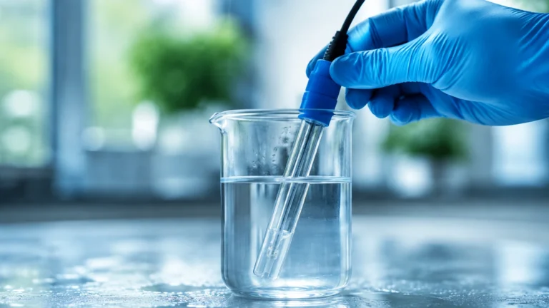
This method utilizes two or more electrodes (usually made of stainless steel, graphite, or titanium) placed in direct contact with the process fluid. An alternating voltage is applied between the electrodes. The resulting current is proportional to the conductivity of the solution.
Contacting sensors are defined by their "cell constant" (K), which is the ratio of the distance between the electrodes to the area of the electrodes.
- Low Cell Constants (K=0.01 to 0.1): Used for high-purity water applications where conductivity is very low.
- Standard Cell Constants (K=1.0): Used for general water treatment and moderately conductive liquids.
- High Cell Constants (K=10.0): Used for seawater or highly concentrated chemical solutions.
Inductive (Toroidal) Conductivity Measurement
Inductive measurement, often called electrodeless or toroidal measurement, uses two wire-wound metal toroids encapsulated in a plastic or ceramic housing. The controller drives an alternating current through the "drive" coil, inducing a current in the surrounding liquid. This liquid current, in turn, induces a current in the "receiver" coil. The strength of this secondary current is proportional to the conductivity of the liquid.
Because the sensor does not have exposed metal electrodes, it is immune to the "polarization" effects that plague contacting sensors in high-conductivity environments. It is also highly resistant to fouling and corrosion.
The Role of the Conductivity Controller
The conductivity controller acts as the brain of the analytical loop. It performs several critical functions beyond simple measurement:
1. Signal Processing: It converts the raw analog signal from the sensor into a digital value expressed in Microsiemens per centimeter (µS/cm) or Millisiemens per centimeter (mS/cm).
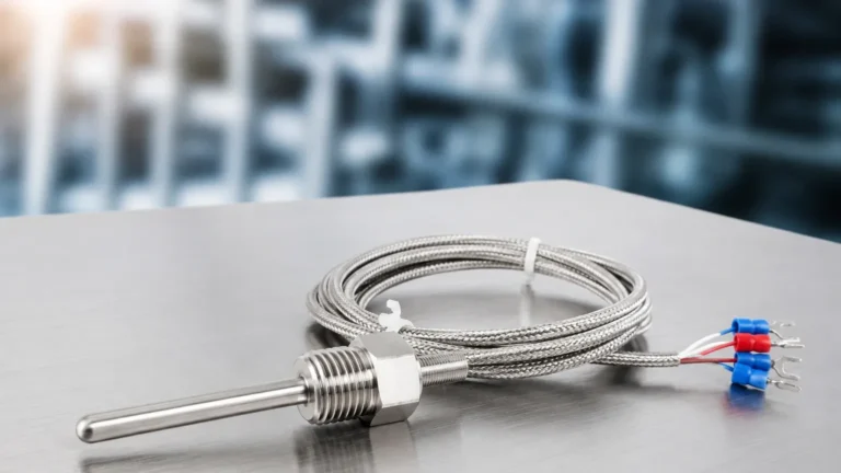
2. Temperature Compensation: Conductivity is highly temperature-dependent; most aqueous solutions increase in conductivity by approximately 2% per degree Celsius. The controller uses input from a temperature sensor (typically a PT100 or PT1000) to normalize the reading to a reference temperature, usually 25°C.
3. Control Logic: Most controllers feature programmable relays. For example, in a cooling tower application, if the conductivity exceeds a setpoint (indicating high mineral concentration), the controller can trigger a "blowdown" valve to drain a portion of the water and replace it with fresh makeup water.
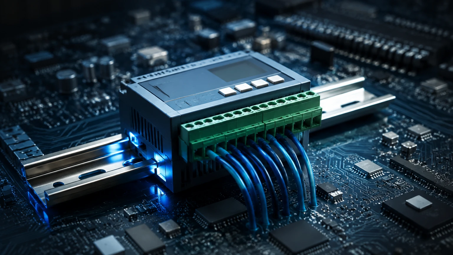
4. Data Transmission: Modern units provide 4-20mA analog outputs or digital communication protocols like RS485 (Modbus RTU) to integrate with PLC or SCADA systems.
Selection Criteria for Conductivity Controllers
Choosing the correct system requires an analysis of the chemical environment and the required precision. The following table provides a general guide for technology selection based on the application environment.
Practical Selection Table
| Application Requirement | Recommended Sensor Type | Typical Range | Key Consideration |
| :— | :— | :— | :— |
| Ultrapure Water (RO/DI) | Contacting (K=0.01 or 0.1) | 0.055 – 20 µS/cm | Requires high precision and temperature accuracy. |
| Potable Water Treatment | Contacting (K=1.0) | 50 – 1000 µS/cm | Standard stainless steel electrodes are sufficient. |
| Wastewater Effluent | Inductive (Toroidal) | 500 – 10,000 µS/cm | Resists fouling from suspended solids and oils. |
| Chemical Concentration | Inductive (Toroidal) | 10 – 2000 mS/cm | Chemical compatibility of the sensor body (e.g., PEEK or PFA). |
| Boiler Blowdown | Contacting (High Temp) | 100 – 5000 µS/cm | Must withstand high pressure and temperature (up to 200°C). |
Installation Considerations
Proper installation is paramount to achieving accurate readings. Even the most advanced conductivity controller will fail to provide useful data if the sensor is incorrectly positioned.
* Flow Direction: For contacting sensors, the liquid should flow through the electrodes to ensure a representative sample and to prevent the buildup of stagnant pockets. For inductive sensors, the "hole" of the toroid must be aligned with the flow.
* Avoid Air Pockets: Sensors should be installed in a vertical pipe with upward flow or on the side of a horizontal pipe. Mounting a sensor on the top of a pipe often leads to air entrapment, which results in erratic or zero-conductivity readings.
* Submergence: In tank installations, ensure the sensor is always fully submerged. For inductive sensors, a minimum clearance (usually 20mm to 50mm) from the tank walls is required to avoid "wall effects" where the magnetic field interacts with the vessel material.
* Cable Integrity: Conductivity signals, especially from contacting sensors in low-range applications, are high-impedance and sensitive to electromagnetic interference (EMI). Always use shielded cables and keep them away from high-voltage power lines.
Limitations and Maintenance
While robust, conductivity controllers have specific limitations that engineers must account for:
* Fouling and Scaling: In contacting sensors, the accumulation of mineral scale or biological film on the electrode surface increases resistance, leading to falsely low conductivity readings. Regular cleaning with a mild acid or detergent is necessary.
* Polarization: At very high conductivities, a layer of ions can build up at the electrode surface of a contacting sensor, creating an internal resistance that skews the measurement. This is why inductive sensors are preferred for high-concentration brine or acids.
* Non-Specificity: Conductivity is a "sum parameter." It tells you the total ionic content but cannot distinguish between different types of ions. For example, it cannot tell the difference between sodium chloride and calcium carbonate in a solution.
Frequently Asked Questions (FAQs)
Q: How often should a conductivity controller be calibrated?
A: For standard water treatment, monthly calibration checks are recommended. In high-purity water or aggressive chemical processes, weekly checks may be necessary. Always use a certified conductivity standard solution that is close to your expected process value.
Q: Can I use a conductivity controller to measure the concentration of sulfuric acid?
A: Yes. Many industrial controllers have built-in conversion tables for common chemicals like H2SO4, NaOH, and HCl. An inductive sensor is highly recommended for this application due to the corrosive nature of the acid.
Q: What is the difference between "Conductivity" and "TDS"?
A: Conductivity measures the ability to pass current, while TDS (Total Dissolved Solids) measures the mass of dissolved minerals. Most controllers can estimate TDS by multiplying the conductivity (in µS/cm) by a factor, typically between 0.5 and 0.7, depending on the water chemistry.
Integration with Process Automation
In modern industrial settings, the conductivity controller does not operate in isolation. It is frequently paired with other instruments, such as those found via the Main Page of Welk’s product lines, to provide a complete picture of the process. For instance, in a large storage tank, a radar level meter might monitor the volume of a chemical, while a conductivity controller ensures the concentration remains within specification during a mixing process.
By selecting the appropriate sensor technology—whether contacting for high-precision pure water or inductive for rugged chemical processing—and ensuring rigorous installation standards, facilities can achieve significant savings in water and chemical usage while protecting downstream equipment from corrosion and scaling. For more information on integrating these analytical tools with your existing level and flow instrumentation, review the technical documentation available through professional measurement solution providers.