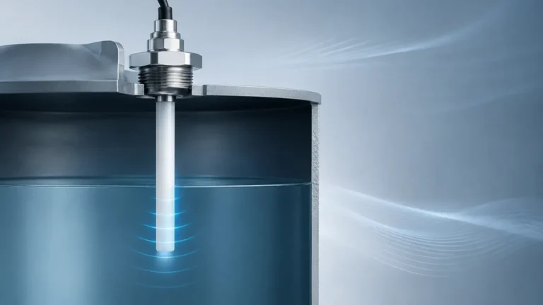
Rtd Sensor
Rtd Sensor
In the landscape of industrial process control, the RTD sensor (Resistance Temperature Detector) stands as one of the most reliable and precise instruments for monitoring thermal conditions. While often viewed as a standalone temperature measurement tool, its integration into complex systems—particularly level measurement—is vital for ensuring data accuracy and operational safety. For engineers and procurement specialists, understanding the nuances of RTD technology is essential for selecting the right equipment for demanding environments such as chemical processing, water treatment, and oil and gas storage.
Understanding the Measurement Principle of RTD Sensors
The operation of an RTD sensor is based on a fundamental physical property: the electrical resistance of a metal changes in a predictable and repeatable manner as its temperature changes. Most industrial RTDs utilize platinum (Pt) because of its excellent corrosion resistance, wide temperature range, and long-term stability.
The Resistance-Temperature Relationship
As the temperature of the metal element increases, the thermal agitation of the atoms within the crystal lattice increases. This higher state of vibration impedes the flow of electrons, thereby increasing electrical resistance. This relationship is mathematically defined by the Callendar-Van Dusen equation, which describes the resistance (R) at a given temperature (t) relative to the resistance at 0°C (R₀).
For most industrial applications, the linear approximation is used:
Rₜ = R₀(1 + αt)
Where:
* Rₜ: Resistance at temperature t.
* R₀: Resistance at 0°C (typically 100 Ω or 1000 Ω).
* α (Alpha): The temperature coefficient of resistance, which for platinum is standardly 0.00385 Ω/Ω/°C.
Common Types of RTD Sensors and Materials
While platinum is the industry standard, other materials are used for specific niche applications. The choice of material and construction type significantly impacts the sensor's performance and longevity.
Material Selection
1. Platinum (Pt): The most common choice. It offers a range from -200°C to +850°C with high accuracy.
2. Nickel (Ni): Less expensive than platinum but has a limited temperature range (typically up to 300°C) and is less linear.
3. Copper (Cu): Offers excellent linearity but is prone to oxidation and is generally limited to lower temperature ranges (-100°C to +150°C).
Construction Methods
* Thin-Film RTDs: These are produced by depositing a thin layer of platinum onto a ceramic substrate. They are compact, vibration-resistant, and cost-effective, making them ideal for many industrial automation applications.
* Wire-Wound RTDs: These consist of a fine platinum wire wrapped around a ceramic or glass core. They offer higher accuracy and are better suited for extreme temperature fluctuations, though they are more sensitive to mechanical vibration.
The Role of RTD Sensors in Industrial Level Measurement
In the context of industrial automation, temperature measurement is rarely an isolated requirement. At Welk, we recognize that accurate level measurement often depends on precise temperature data. This is particularly true for technologies available on our Main Page, where RTD sensors are frequently integrated into or used alongside level transmitters.
Temperature Compensation in Hydrostatic Level Sensors
Hydrostatic level transmitters calculate the height of a liquid based on the pressure exerted by the liquid column. However, the density of a liquid changes with temperature. An RTD sensor provides the real-time thermal data necessary for the transmitter’s electronics to compensate for these density shifts, ensuring the level reading remains accurate regardless of seasonal or process-induced temperature changes.
Sound Speed Correction in Ultrasonic Sensors
Ultrasonic level sensors measure the time it takes for a sound wave to travel to the liquid surface and back. The speed of sound in air (or gas) is highly dependent on temperature. Without an integrated RTD sensor to provide a local temperature reference, an ultrasonic sensor could produce errors of up to 1% for every 5°C change in temperature.
Selection Criteria for RTD Sensors in Process Environments
Choosing the correct RTD involves more than just selecting a temperature range. Engineers must consider accuracy classes, environmental factors, and the physical constraints of the installation site.
Accuracy Classes (IEC 60751)
RTDs are categorized into classes based on their tolerance levels. The following table outlines the standard tolerances for Pt100 sensors:
| Class | Tolerance at 0°C | Tolerance at 100°C | Typical Application |
| :— | :— | :— | :— |
| Class AA (1/3 DIN) | ±0.10°C | ±0.27°C | Laboratory and high-precision process control |
| Class A | ±0.15°C | ±0.35°C | Critical industrial processes and custody transfer |
| Class B | ±0.30°C | ±0.80°C | General-purpose industrial monitoring |
| Class C | ±0.60°C | ±1.60°C | Non-critical HVAC and basic monitoring |
Environmental Considerations
* Chemical Compatibility: For corrosive liquids, RTD sheaths should be constructed from 316L Stainless Steel, Hastelloy, or PTFE-coated materials.
* Pressure Requirements: In high-pressure tanks, the RTD must be housed in a thermowell designed to withstand the process pressure and flow-induced vibrations.
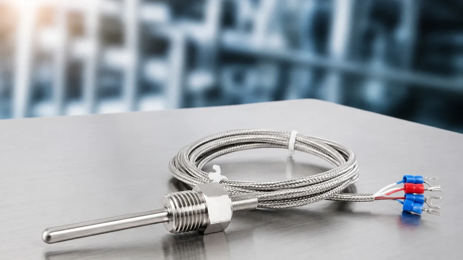
Wiring Configurations: 2-Wire, 3-Wire, and 4-Wire Systems
One of the most critical decisions in RTD selection is the wiring configuration. Because an RTD measures resistance, the resistance of the lead wires themselves can introduce significant errors.
1. 2-Wire Configuration: The simplest but least accurate. The lead wire resistance is added directly to the sensor resistance, leading to a constant positive error. It is only recommended for very short distances or when high accuracy is not required.
2. 3-Wire Configuration: The most common industrial standard. It uses a third wire to measure the lead resistance and subtracts it from the total measurement. This assumes all three wires have identical resistance.
3. 4-Wire Configuration: The most accurate method. It uses two wires to carry the excitation current and two separate wires to measure the voltage drop across the RTD element. This completely eliminates the impact of lead wire resistance and is used in Class A or Class AA applications.
Installation Best Practices and Maintenance
Proper installation is paramount to ensuring the longevity and accuracy of an RTD sensor. Incorrect placement can lead to "stem conduction" errors, where heat is transferred away from the sensing element through the probe sheath.
Installation Checklist
* Immersion Depth: A general rule of thumb is to immerse the RTD to a depth of at least 10 times the diameter of the protection tube to minimize stem conduction errors.
* Thermowell Use: In pressurized or high-velocity flows, always use a thermowell. This allows the sensor to be replaced without breaking the process seal or draining the tank.
* Orientation: In small diameter pipes, the RTD should be installed at an angle or in an elbow against the flow to maximize the contact time with the fluid.
* Vibration Dampening: If the installation site is subject to heavy vibration (e.g., near pumps), use thin-film RTDs or specialized vibration-resistant housings.
Maintenance Guidance
RTDs are known for their stability, but they are not maintenance-free. Annual calibration checks are recommended. If a sensor shows a "drift" in readings, it may be due to moisture ingress in the housing or mechanical stress on the element. Always check the insulation resistance; a low insulation resistance (below 100 MΩ at 100V DC) usually indicates a failing seal.
Limitations and Comparison with Thermocouples
While RTD sensors offer superior accuracy and stability, they are not always the best choice for every application. Understanding their limitations compared to thermocouples is essential for engineering design.
| Feature | RTD Sensor | Thermocouple |
| :— | :— | :— |
| Temperature Range | -200°C to +850°C | -200°C to +2300°C |
| Accuracy | High (±0.1°C to ±0.6°C) | Medium (±0.5°C to ±2.2°C) |
| Stability | Excellent (Minimal drift) | Low (Prone to aging/drift) |
| Response Time | Slower (Generally 1-10s) | Fast (Often <1s) |
| Durability | Fragile (Sensitive to vibration) | Rugged (High vibration resistance) |
| Cost | Higher | Lower |
Self-Heating Risk: A unique limitation of RTDs is self-heating. Because the sensor requires an excitation current to measure resistance, the current itself generates a small amount of heat. If the excitation current is too high (typically above 1 mA), it can cause the sensor to read higher than the actual process temperature.
Frequently Asked Questions (FAQs)
Q: Can I use a Pt1000 sensor instead of a Pt100?
A: Yes, Pt1000 sensors offer higher resolution and are less sensitive to lead wire resistance in 2-wire configurations. However, they are more susceptible to self-heating and may not be compatible with older PLC or transmitter inputs designed specifically for Pt100.
Q: How do I know if my RTD has failed?
A: A complete failure usually results in an "Open Circuit" (infinite resistance) or a "Short Circuit" (near zero resistance). If the readings are simply erratic, check for loose terminal connections or moisture in the junction box.
Q: What is the difference between a 3-wire RTD and a 4-wire RTD in terms of real-world accuracy?
A: In a 10-meter cable run, a 3-wire system might have an error of 0.1°C to 0.5°C depending on wire uniformity. A 4-wire system will have zero error from the lead wires, making it essential for high-precision thermal balancing in chemical reactors.
Q: Why is 316 Stainless Steel the standard for RTD sheaths?
A: 316 Stainless Steel offers an excellent balance of thermal conductivity, mechanical strength, and corrosion resistance against most industrial chemicals and water treatment additives.
For industrial operators seeking to integrate temperature and level measurement, selecting high-quality RTD sensors is a prerequisite for system reliability. By adhering to proper wiring standards and installation depths, facilities can ensure their process data remains accurate over years of continuous operation.