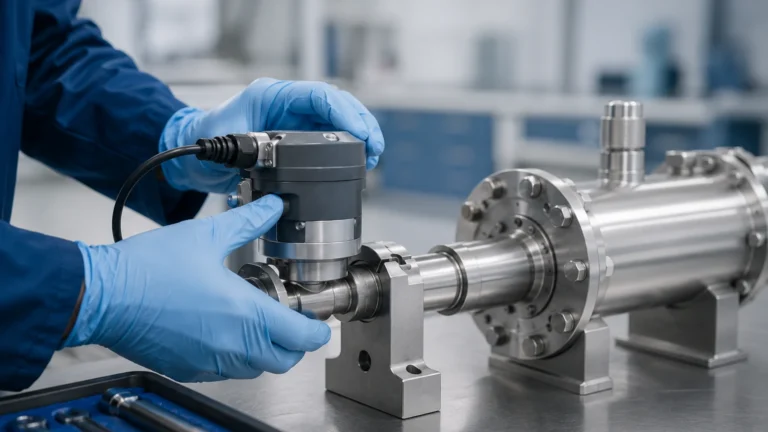
Differential Pressure Transmitter for Hvac
Differential Pressure Transmitter for Hvac
In the complex landscape of modern building automation and industrial climate control, the differential pressure transmitter for HVAC (Heating, Ventilation, and Air Conditioning) serves as a critical sensory component. These devices are responsible for monitoring and controlling air flow, filter efficiency, and room pressurization, ensuring that environments remain safe, comfortable, and energy-efficient. Whether applied in high-rise commercial offices, sterile cleanrooms, or industrial manufacturing plants, understanding the engineering principles and selection criteria for these transmitters is essential for any facility manager or systems engineer.
Measurement Principles of Differential Pressure Transmitters
A differential pressure (DP) transmitter operates by measuring the difference between two pressure points in a system. Unlike a standard pressure gauge that measures pressure relative to the atmosphere (gauge pressure), a DP transmitter utilizes two ports: a high-pressure port (H) and a low-pressure port (L). The resulting measurement is the mathematical delta between these two inputs.
The Sensing Element
Most modern HVAC transmitters employ one of two primary sensing technologies:
1. Piezoresistive Sensors: These utilize a silicon or ceramic diaphragm with integrated strain gauges. When pressure is applied, the diaphragm deforms slightly, changing the electrical resistance of the strain gauges. This change is proportional to the pressure and is converted into an electronic signal (typically 4-20mA or 0-10V).
2. Capacitive Sensors: In this design, a sensing diaphragm is positioned between two fixed capacitor plates. As pressure shifts the diaphragm, the capacitance between the diaphragm and the plates changes. Capacitive sensors are known for their high sensitivity and stability, making them ideal for the very low pressure ranges (often as low as 25 Pa or 0.1 inWC) found in air-side HVAC applications.
In liquid-based HVAC systems, such as chilled water loops, the principle remains the same, but the construction of the transmitter is more robust to handle higher static pressures and potential water hammer effects. For engineers looking for broader measurement solutions, including liquid level and flow monitoring, visiting the Main Page of a specialized manufacturer can provide insights into how these pressure principles translate to hydrostatic level measurement.
Key Applications in HVAC Systems
The differential pressure transmitter for HVAC is a versatile tool used across several subsystems. Its primary roles include:
Filter Status Monitoring
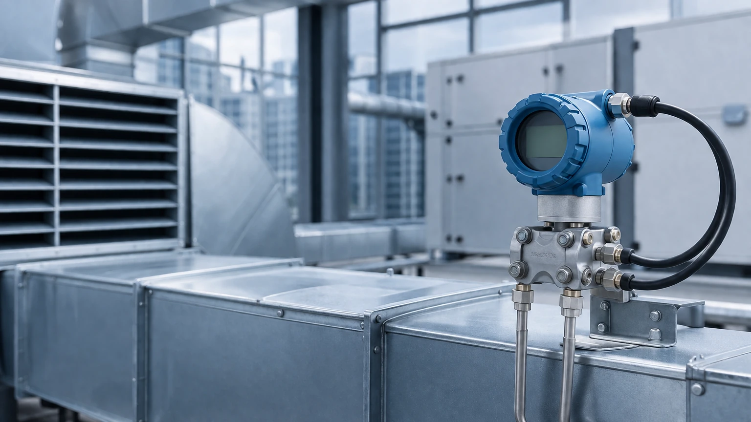
Air handling units (AHUs) rely on filters to maintain indoor air quality. As dust and debris accumulate, the resistance to air flow increases. By placing the high-pressure port upstream of the filter and the low-pressure port downstream, the transmitter measures the pressure drop. When the differential pressure reaches a pre-set limit (e.g., 250 Pa), the building management system (BMS) triggers a maintenance alert for filter replacement.
Variable Air Volume (VAV) Control
In VAV systems, the transmitter is used to measure the velocity pressure across a pitot tube or flow station. This data allows the controller to adjust the damper position, ensuring that the correct volume of air is delivered to specific zones regardless of fluctuations in the main duct pressure.
Building and Room Pressurization
Cleanrooms, laboratories, and hospitals require precise pressure relationships between rooms to prevent cross-contamination. A DP transmitter measures the difference between the controlled room and the adjacent corridor. Typically, a positive pressure (e.g., +12 Pa) is maintained in cleanrooms to keep contaminants out, while negative pressure is used in isolation wards to keep pathogens contained.
Practical Selection Criteria
Selecting the right differential pressure transmitter for HVAC requires balancing technical requirements with cost-effectiveness. The following factors are paramount:
* Pressure Range: HVAC air-side applications typically require very low ranges (0–100 Pa, 0–500 Pa, or 0–2500 Pa). Water-side applications may require ranges up to 10 bar (145 PSI).
* Accuracy: For general ventilation, an accuracy of ±1% of full scale (FS) is usually sufficient. For critical cleanroom applications, ±0.25% or ±0.5% FS may be required.
* Output Signal: While 4-20mA is the industrial standard due to its noise immunity over long distances, 0-10V is common in smaller commercial BMS installations. Digital protocols like Modbus or BACnet are increasingly popular for direct integration into smart building networks.
* Media Compatibility: Ensure the transmitter is rated for the medium. Air-side transmitters are designed for dry, non-corrosive gases, while water-side transmitters must feature stainless steel or specialized alloy wetted parts.
Technical Selection Table
| Feature | Air-Side (Duct/Filter) | Water-Side (Pump/Chiller) | Cleanroom/Lab |
| :— | :— | :— | :— |
| Typical Range | 0 to 500 Pa (0–2 inWC) | 0 to 6 bar (0–87 PSI) | -25 to +25 Pa (-0.1 to +0.1 inWC) |
| Sensing Tech | Capacitive / Piezoresistive | Piezoresistive / Strain Gauge | High-precision Capacitive |
| Accuracy | ±1.0% FS | ±0.5% FS | ±0.25% to ±0.5% FS |
| Burst Pressure | Low (e.g., 5x range) | High (e.g., 3x static pressure) | Moderate |
| Environment | IP54 / IP65 | IP67 (NEMA 4X) | IP65 (Flush Mount) |
Installation Considerations and Best Practices
Proper installation is as important as the device selection itself. Incorrectly installed transmitters often lead to "ghost" readings or premature failure.
1. Port Orientation: For air-side applications, it is best to mount the transmitter vertically. If moisture or condensation is possible in the sensing lines, the tubing should loop downward before entering the transmitter to act as a moisture trap.
2. Static Pressure Probes: When measuring duct pressure, the probe must be inserted perpendicular to the airflow. If the probe is angled, it will capture velocity pressure instead of static pressure, leading to inaccurate readings.
3. Tubing Length: While modern transmitters can handle significant tubing lengths, keeping runs under 15 meters (50 feet) minimizes signal lag and the risk of kinks or leaks.
4. Zeroing the Sensor: Before commissioning, the transmitter should be zeroed at atmospheric pressure. Many high-quality HVAC transmitters feature a manual or automatic "auto-zero" button to calibrate the sensor to its installed orientation.
Limitations and Common Risks
While highly reliable, the differential pressure transmitter for HVAC has specific limitations:
* Overpressure Events: If a valve is closed too quickly in a liquid system (water hammer) or if a high-pressure compressed air line is accidentally connected to a low-pressure sensor, the sensing diaphragm can be permanently deformed.
* Temperature Drift: Sensors are calibrated at room temperature. In environments with extreme temperature fluctuations (e.g., rooftop AHUs in winter), the accuracy may drift. Selecting a transmitter with temperature compensation is vital for outdoor installations.
* Contamination: In exhaust systems carrying grease or heavy particulates, the sensing ports can become clogged. In these cases, the use of a diaphragm seal or air-purge system may be necessary, though these are more common in heavy industrial processes than standard commercial HVAC.
Frequently Asked Questions (FAQ)
Q: What is the difference between a pressure switch and a differential pressure transmitter?
A: A pressure switch is a binary device; it only indicates if the pressure is above or below a certain setpoint (On/Off). A differential pressure transmitter provides a continuous analog or digital signal representing the actual pressure value, allowing for precise control and trending.
Q: Can I use an air-pressure transmitter for water applications?
A: No. Air-pressure transmitters are typically designed for non-conductive, non-corrosive gases and cannot withstand the pressures or the chemical nature of water loops. Water-side DP transmitters use different internal materials and seals.
Q: How often should an HVAC DP transmitter be calibrated?
A: For standard commercial buildings, an annual check is usually sufficient. For regulated environments like pharmaceutical labs or hospitals, semi-annual or quarterly calibration may be required to meet compliance standards.
Q: Why is my transmitter reading a negative value when the fan is on?
A: This usually indicates that the high and low pressure tubes are swapped. Ensure the high-pressure port is connected to the point of higher pressure (e.g., upstream of a filter or the discharge side of a fan).
Conclusion
The differential pressure transmitter for HVAC is a foundational element of modern infrastructure. By accurately monitoring the subtle differences in air and liquid pressure, these devices enable the sophisticated control strategies required for energy efficiency and occupant safety. When selecting a unit, engineers must look beyond the price tag and consider the long-term stability, accuracy, and environmental resilience of the sensor. For those involved in broader industrial automation, exploring integrated solutions for level, flow, and pressure measurement can lead to more cohesive and reliable system designs. For more information on industrial-grade measurement instruments, you can Review product options and application support to find the right fit for your specific project requirements.
Download Differential Pressure Transmitter for Hvac as a PDF