Calibrate Pressure Transducer
Calibrate Pressure Transducer
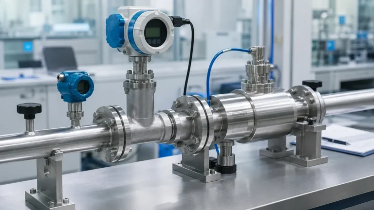
In industrial process control, the accuracy of level and pressure measurements is fundamental to operational safety, efficiency, and product quality. Pressure transducers are the workhorses of these systems, converting physical force into measurable electrical signals. However, like all precision instruments, they are subject to drift, environmental wear, and electronic aging. To maintain the integrity of a system, engineers and technicians must regularly calibrate pressure transducer units to ensure they remain within their specified tolerance bands.
This guide provides a technical overview of pressure transducer principles, the step-by-step calibration process, and best practices for selection and installation in industrial environments.
Measurement Principles of Pressure Transducers
Before discussing how to calibrate pressure transducer equipment, it is essential to understand the underlying physics. In the context of level measurement, pressure transducers typically operate on the principle of hydrostatic pressure.
Hydrostatic pressure is the force exerted by a fluid at equilibrium at a given point within the fluid, due to the force of gravity. The relationship is defined by the formula:
P = ρ × g × h
Where:
- P is the hydrostatic pressure (Pa or bar).
- ρ (rho) is the density of the liquid (kg/m³).
- g is the acceleration due to gravity (approximately 9.81 m/s²).
- h is the height of the liquid column above the sensor (m).
Sensor Technologies
Most industrial pressure transducers utilize one of three primary sensing technologies:
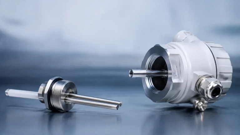
1. Piezoresistive Strain Gauges: These use a diaphragm with integrated resistors. When pressure deforms the diaphragm, the resistance changes, which is measured via a Wheatstone bridge circuit.
2. Capacitive Sensors: These measure the change in capacitance between a sensing diaphragm and a fixed metal plate. They are known for high sensitivity and stability in low-pressure applications.
3. Piezoelectric Sensors: These generate an electric charge when mechanical stress is applied. These are typically used for dynamic pressure changes rather than static level measurement.
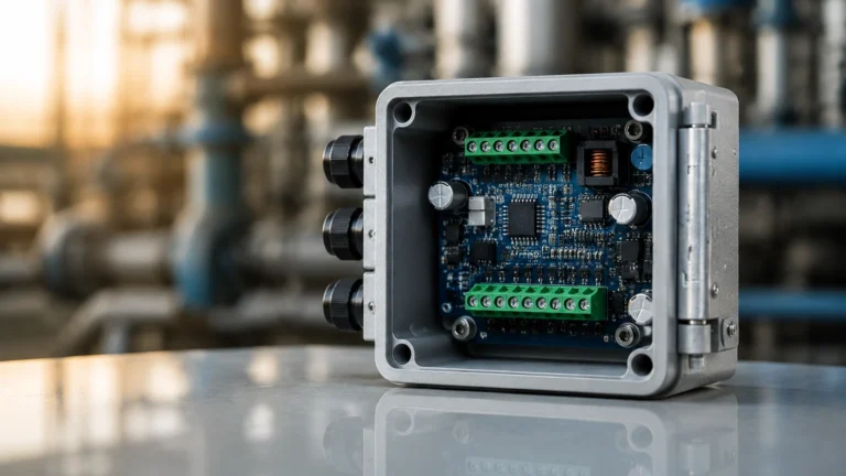
Modern instruments, such as those offered by Welk, often integrate these sensors with advanced electronics to provide 4-20mA, HART, or Modbus outputs, facilitating easier integration into PLC and SCADA systems.
Why Calibration is Essential
Calibration is the process of comparing the output of a device under test (DUT) against a reference standard of known accuracy. For a pressure transducer, this ensures that the electrical output (e.g., 4mA at 0 bar and 20mA at 10 bar) accurately represents the physical reality of the process.
Common reasons for calibration include:
- Sensor Drift: Over time, the mechanical properties of the diaphragm or the electronic components may shift slightly.
- Environmental Factors: Extreme temperatures, vibration, and pressure spikes can alter the sensor's performance.
- Regulatory Compliance: Many industries, such as pharmaceuticals and food processing, require documented calibration traces to meet ISO or FDA standards.
- Density Changes: If the media being measured changes in density (due to temperature or concentration changes), the transducer must be recalibrated or compensated to reflect the true level.
Step-by-Step: How to Calibrate Pressure Transducer
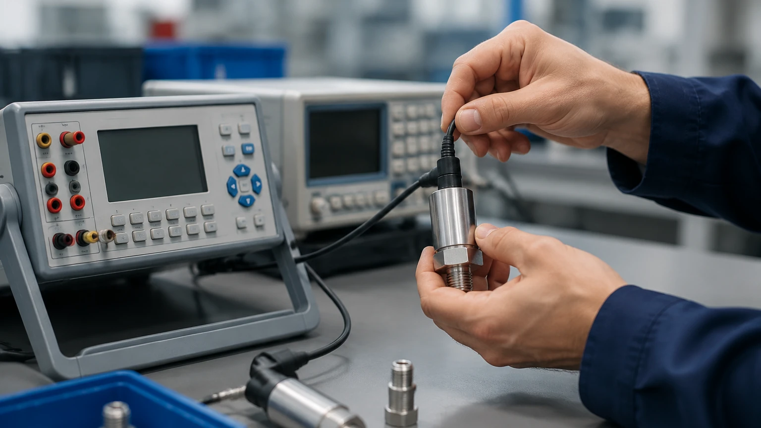
Calibration can be performed in a laboratory (bench calibration) or in the field (loop calibration). The following procedure outlines a standard 5-point calibration check.
1. Preparation and Safety
- Isolate the Sensor: Ensure the transducer is isolated from the process pressure using a block-and-bleed valve.
- Vent to Atmosphere: For gauge pressure sensors, ensure the reference side is open to the atmosphere.
- Power Supply: Connect the transducer to a stable DC power source (typically 24V DC).
- Tools Required: A high-accuracy pressure calibrator (or deadweight tester), a digital multimeter (DMM) to measure the mA output, and a HART communicator if the device is smart-enabled.
2. Zero Adjustment
With no pressure applied (0% of the range), the transducer should output exactly 4.000 mA. If the reading is outside the manufacturer’s tolerance (e.g., 4.05 mA), use the "Zero" adjustment screw or the digital interface to bring it back to 4.000 mA.
3. Span Adjustment
Apply the maximum rated pressure for the application (100% of the range) using a pressure pump or deadweight tester. The output should be 20.000 mA. Use the "Span" or "Gain" adjustment to correct any deviation.
4. Linearity and Hysteresis Check
To ensure the sensor is accurate across its entire range, perform a 5-point check:
- 0%: 4mA
- 25%: 8mA
- 50%: 12mA
- 75%: 16mA
- 100%: 20mA
Repeat these steps in descending order (100% down to 0%) to check for hysteresis—the difference in readings when approaching a point from different directions.
5. Documentation
Record the "As-Found" (before adjustment) and "As-Left" (after adjustment) data. Calculate the error percentage relative to the Full Scale (FS). If the error exceeds the allowable limit, the unit may require repair or replacement.
Selection Criteria for Pressure Transducers
Choosing the right instrument is as important as proper calibration. Engineers should evaluate the following criteria when selecting a level measurement solution:
| Criteria | Consideration | Recommended Technology |
| :— | :— | :— |
| Media Type | Corrosive, viscous, or clean liquids | Diaphragm seals for corrosive media |
| Installation | Top-mount vs. Side-mount | Hydrostatic submersible for deep wells |
| Accuracy | Required precision for the process | Radar for high precision; Pressure for standard |
| Temperature | Operating and ambient temperature | Compensated transducers for high temp |
| Pressure Type | Gauge, Absolute, or Differential | Differential for pressurized tanks |
For a wide range of industrial-grade sensors and technical documentation, you can visit the Main Page to review product options and application support.
Installation Considerations and Limitations
Proper installation is a prerequisite for successful calibration. If a sensor is installed incorrectly, even the most precise calibration will not yield accurate results.
Mounting Position
Pressure transducers are sensitive to orientation. If a transducer is calibrated in a vertical position but installed horizontally, the weight of the internal oil fill or the diaphragm itself may cause a zero shift. Always calibrate in the orientation in which the device will be used.
Venting
For gauge pressure measurements, the back of the diaphragm must be vented to the atmosphere. Submersible transducers often use a vented cable. If this vent becomes blocked or moisture enters the tube, the readings will fluctuate with changes in barometric pressure.
Impulse Lines
In differential pressure applications, impulse lines connect the process to the transducer. These lines must be sloped correctly (to prevent gas pockets in liquid lines or liquid in gas lines) and kept at a consistent temperature to avoid density variations.
Limitations of Pressure Transducers
- Density Sensitivity: Since hydrostatic pressure depends on density, any change in the liquid's temperature or composition will introduce error unless a compensation system is used.
- Mechanical Wear: Metal diaphragms can suffer from fatigue or "hydrogen embrittlement" in specific chemical environments.
- Turndown Ratio: While many smart transmitters allow for a wide turndown (e.g., 100:1), accuracy usually degrades as the range is compressed.
Frequently Asked Questions (FAQ)
Q: How often should I calibrate pressure transducer units?
A: Most industrial standards recommend an annual calibration. However, in critical or harsh environments, semi-annual or quarterly checks may be necessary. Always follow the manufacturer's recommendations and internal quality protocols.
Q: Can I calibrate a transducer without a pressure source?
A: You can perform an electronic "loop check" to verify that the PLC is receiving the 4-20mA signal correctly, but you cannot verify the accuracy of the sensing element without applying a known physical pressure.
Q: What is the difference between a pressure transducer and a pressure transmitter?
A: While the terms are often used interchangeably, a *transducer* generally refers to a device that outputs a low-level voltage (e.g., 0-100mV), while a *transmitter* includes circuitry to convert that signal into a standardized current loop (4-20mA) or digital signal.
Q: How does temperature affect calibration?
A: Temperature can cause the materials in the sensor to expand or contract. High-quality transducers include internal temperature compensation, but significant shifts outside the compensated range will require recalibration at the operating temperature.
Conclusion
To calibrate pressure transducer units effectively, one must combine an understanding of fluid mechanics with precise electrical measurement. Regular calibration not only ensures that your level measurement remains accurate but also serves as a diagnostic tool to identify potential sensor failures before they lead to process downtime.
By following standardized procedures and selecting high-quality instruments tailored to your specific application—whether it be water treatment, chemical processing, or oil and gas—you ensure the long-term reliability of your automation systems. For more detailed technical specifications on radar, ultrasonic, and hydrostatic level measurement technologies, refer to the resources available on the Main Page.