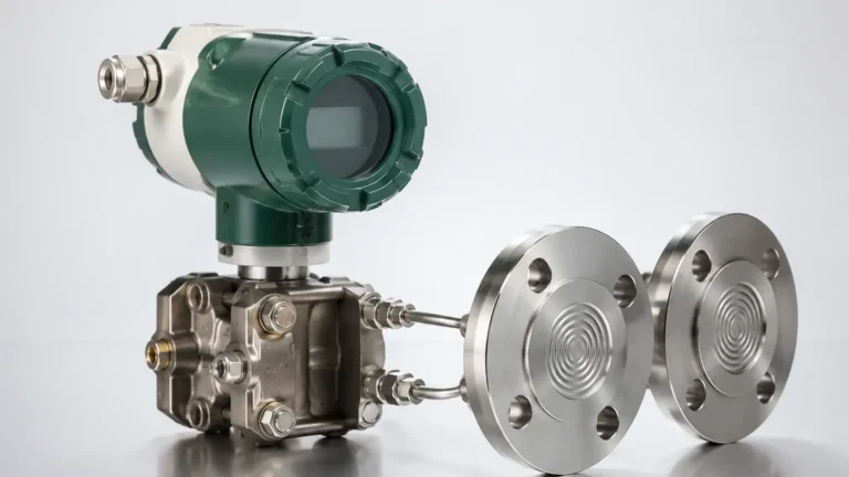
Analyzer Transmitter
Analyzer Transmitter
In the landscape of industrial process control, the accuracy and reliability of data depend heavily on the interface between the physical medium and the control system. An analyzer transmitter serves as this critical bridge. While the term is frequently associated with liquid analysis (such as pH or conductivity), in the context of level measurement, it refers to the sophisticated electronic unit that processes raw signals from a primary sensor—be it radar, ultrasonic, or hydrostatic—and converts them into a standardized, actionable output.
For engineers and plant managers, selecting the right analyzer transmitter is not merely about choosing a sensor; it is about ensuring the electronic "brain" of the measurement system can handle the complexities of the specific industrial environment. This guide explores the fundamental principles, selection criteria, and practical applications of these instruments within the level measurement sector.
Understanding the Role of an Analyzer Transmitter in Level Measurement
An analyzer transmitter is designed to perform three primary functions: excitation, signal processing, and communication.
1. Excitation: The transmitter provides the necessary power or pulse to the sensor (e.g., sending an electrical pulse to a piezoelectric crystal in an ultrasonic sensor).
2. Signal Processing: Once the sensor receives a return signal (an echo or a pressure change), the transmitter filters out noise, compensates for environmental variables like temperature or vapor, and calculates the final measurement value.
3. Communication: The calculated value is then converted into a protocol compatible with the facility's Distributed Control System (DCS) or Programmable Logic Controller (PLC), typically via 4-20mA loops, HART, Modbus, or Profibus.
Modern analyzer transmitters, such as those featured on the Main Page of industrial instrumentation providers, often include advanced diagnostics. These allow operators to visualize echo curves or monitor the health of the sensor in real-time, which is essential for predictive maintenance in high-stakes environments like chemical processing or oil and gas storage.
Core Measurement Principles and Technologies
Before selecting a transmitter, it is essential to understand the underlying physics of the sensors they support. Each technology has distinct requirements for how the analyzer transmitter processes the incoming data.
Radar Level Measurement (Non-Contact and Guided)
Radar technology relies on the transmission of electromagnetic waves. The analyzer transmitter measures the time-of-flight from the emission of the signal to the reception of the reflected echo from the product surface.
* FMCW (Frequency Modulated Continuous Wave): The transmitter sends a continuous signal with a constantly changing frequency. The difference between the emitted and received frequency is proportional to the distance. This requires high-speed signal processing within the transmitter to maintain accuracy.
* Pulse Radar: The transmitter measures the micro-durations of discrete microwave pulses.
Ultrasonic Level Measurement
Ultrasonic transmitters use sound waves (typically 20 kHz to 200 kHz). The transmitter calculates distance based on the time it takes for a sound pulse to travel to the surface and back. Because the speed of sound is highly dependent on air temperature, a high-quality analyzer transmitter must include an integrated temperature sensor or an input for an external probe to perform real-time compensation.
Hydrostatic Pressure Measurement
In this principle, the transmitter analyzes the pressure exerted by a liquid column. The relationship is defined by the formula: *P = ρgh* (Pressure = density × gravity × height). The analyzer transmitter must be calibrated for the specific gravity of the liquid. In pressurized tanks, a differential pressure transmitter is used to subtract the head pressure from the total pressure to isolate the liquid level.
Key Evaluation Criteria for Selecting a Transmitter
Choosing an analyzer transmitter requires a detailed analysis of the process conditions and the required data output.
1. Accuracy and Repeatability
In inventory management, a few millimeters of error can translate to significant financial discrepancies. High-end radar transmitters can offer accuracies of ±1 mm, while ultrasonic versions typically range from ±2 mm to ±5 mm. Repeatability is equally important for process stability, ensuring the transmitter provides the same reading under identical conditions.
2. Environmental Resilience
Industrial environments are often harsh. The transmitter housing must meet specific Ingress Protection (IP) ratings, such as IP67 or IP68, to withstand dust and moisture. Furthermore, if the transmitter is installed in a hazardous area (e.g., near flammable gases), it must carry ATEX, IECEx, or UL certifications for intrinsic safety or explosion-proof operation.
3. Media Characteristics
The physical properties of the medium—such as the dielectric constant (Dk) for radar, or the presence of foam and steam for ultrasonic—dictate the transmitter’s signal processing requirements. An analyzer transmitter with "False Echo Suppression" is vital when internal tank obstructions (like agitators or ladders) are present.
4. Output and Integration
While 4-20mA remains the industry standard, the rise of Industry 4.0 has increased demand for digital protocols. A transmitter with HART (Highway Addressable Remote Transducer) allows for digital configuration and diagnostics to be superimposed on the analog signal, providing more data without additional wiring.
Technical Comparison Table
The following table provides a general comparison of common technologies used with analyzer transmitters in level applications.
| Feature | Radar (80GHz) | Ultrasonic | Hydrostatic | Magnetic Gauge |
| :— | :— | :— | :— | :— |
| Measurement Range | Up to 120m | Up to 30m | Up to 200m | Up to 6m (standard) |
| Accuracy | ±1 mm | ±0.25% of range | ±0.1% to 0.5% | ±5 mm to 10 mm |
| Pressure Limit | Up to 160 bar | Ambient (mostly) | Up to 400 bar | Up to 200 bar |
| Temp. Range | -196°C to +450°C | -40°C to +80°C | -40°C to +125°C | -196°C to +400°C |
| Effect of Vapor | None | Significant | None | None |
| Contact with Media | Non-contact | Non-contact | Contact | Contact |
Installation Guidelines and Best Practices
Even the most advanced analyzer transmitter will fail to provide accurate data if installed incorrectly. Engineering teams should adhere to the following checklists:
Mounting Position
* Avoid the Center: For ultrasonic and radar transmitters, avoid mounting the sensor in the exact center of a domed tank, as this can concentrate multiple reflections and confuse the analyzer.
* Nozzle Length: Ensure the sensor antenna or transducer extends past the mounting nozzle. If the nozzle is too long, the transmitter may detect the nozzle edge as the liquid level.
* Inflow Interference: Never install the transmitter directly above the tank's filling inlet. The turbulence and falling liquid will disrupt the signal.
Wiring and Grounding
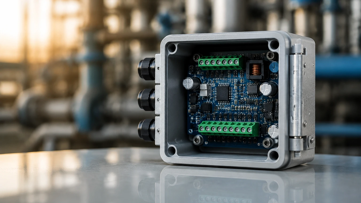
To prevent signal interference, shielded cables should be used for the 4-20mA loop. The transmitter housing must be properly grounded to the vessel or the plant's common ground to dissipate static electricity and prevent electromagnetic interference (EMI).
Calibration
Field calibration is often necessary. This involves setting the "Zero" (4mA) point at the bottom of the tank and the "Span" (20mA) point at the maximum desired level. Many modern transmitters support "dry calibration," where the dimensions are entered manually into the analyzer transmitter software without needing to fill the tank.
Limitations and Common Operational Risks
While analyzer transmitters are robust, they are not universal solutions. Understanding their limitations prevents costly downtime.
* Dielectric Limits: Radar transmitters struggle with low-dielectric materials (like certain oils or liquid gases) because the signal passes through the medium rather than reflecting off it. In these cases, guided wave radar or high-frequency (80GHz) transmitters are required.
* Acoustic Noise: Ultrasonic transmitters can be affected by high-frequency noise from pneumatic valves or heavy machinery, which the analyzer may misinterpret as a return echo.
* Build-up and Coating: In applications involving sticky resins or wastewater, material can build up on the sensor face. While some transmitters feature "self-cleaning" algorithms or high-gain modes to penetrate coating, manual cleaning may still be required periodically.
* Vacuum Conditions: Ultrasonic waves cannot travel through a vacuum. For vacuum distillation columns, radar or hydrostatic transmitters are the only viable options.
Frequently Asked Questions (FAQ)
Q: Can one analyzer transmitter be used for multiple types of sensors?
A: Generally, no. Transmitters are typically designed for a specific sensing technology (e.g., a radar transmitter is circuitry-specific to microwave processing). However, some universal controllers can accept various 4-20mA inputs from different sensors and act as a centralized display and relay unit.
Q: What is the difference between a 2-wire and a 4-wire transmitter?
A: A 2-wire transmitter uses the same pair of wires for both power and the 4-20mA signal, making it easier to install. A 4-wire transmitter has separate pairs for power (often 110/220V AC or 24V DC) and signal, which is usually necessary for power-intensive devices like heated sensors or high-power radar.
Q: How does foam affect the analyzer transmitter?
A: Foam can either absorb the signal (ultrasonic and radar) or reflect it prematurely. If foam is light and airy, radar often sees through it to the liquid. If it is dense and conductive, the transmitter may read the top of the foam. Hydrostatic transmitters are generally unaffected by foam as they measure mass/pressure.
Q: Is it possible to update the software on an analyzer transmitter?
A: Yes, many modern industrial transmitters allow for firmware updates via a HART modem or a dedicated service port. This can improve signal processing algorithms or add new communication features without replacing the hardware.
For technical specifications and to explore the full range of industrial level measurement hardware, professionals are encouraged to review the Main Page for detailed product data sheets and application support. Selecting the correct analyzer transmitter is a foundational step in achieving process efficiency and safety in any modern industrial facility.