Digital vs Analogue Pd Testing
Digital vs Analogue Pd Testing
In the realm of industrial automation and process control, the reliability of instrumentation is paramount. Whether monitoring the level of corrosive chemicals in a storage tank or managing water treatment facilities, the electronic integrity of sensors determines the safety and efficiency of the entire operation. One critical diagnostic method used to ensure the longevity of high-voltage components and sensitive electronic circuitry within these instruments is Partial Discharge (PD) testing. When evaluating diagnostic equipment or specifying requirements for new installations, engineers often face the choice between traditional methods and modern innovations: digital vs analogue pd testing.
Understanding the nuances between these two approaches is essential for maintenance professionals and plant engineers who rely on accurate level measurement solutions. This guide explores the principles of PD testing, compares analogue and digital methodologies, and discusses their implications for industrial level measurement technologies.
Principles of Partial Discharge Testing
Partial Discharge (PD) refers to a localized electrical discharge that only partially bridges the insulation between conductors. While seemingly minor, these discharges are progressive. Over time, they erode insulation, leading to catastrophic failure of electrical components, including the power supplies and signal processing units found in advanced level meters.
How PD is Measured
PD testing detects the high-frequency electromagnetic pulses or acoustic signals emitted during a discharge event. In the context of industrial instrumentation, such as radar level meters or ultrasonic sensors, PD testing is typically conducted during the manufacturing phase (Quality Assurance) or during periodic field maintenance of the electrical infrastructure supporting the sensors.
Measurement involves capturing the apparent charge, usually measured in picocoulombs (pC), and analyzing the frequency and phase of the occurrences relative to the voltage cycle. The goal is to identify insulation defects before they result in unplanned downtime or equipment damage.
Analogue PD Testing: The Traditional Approach
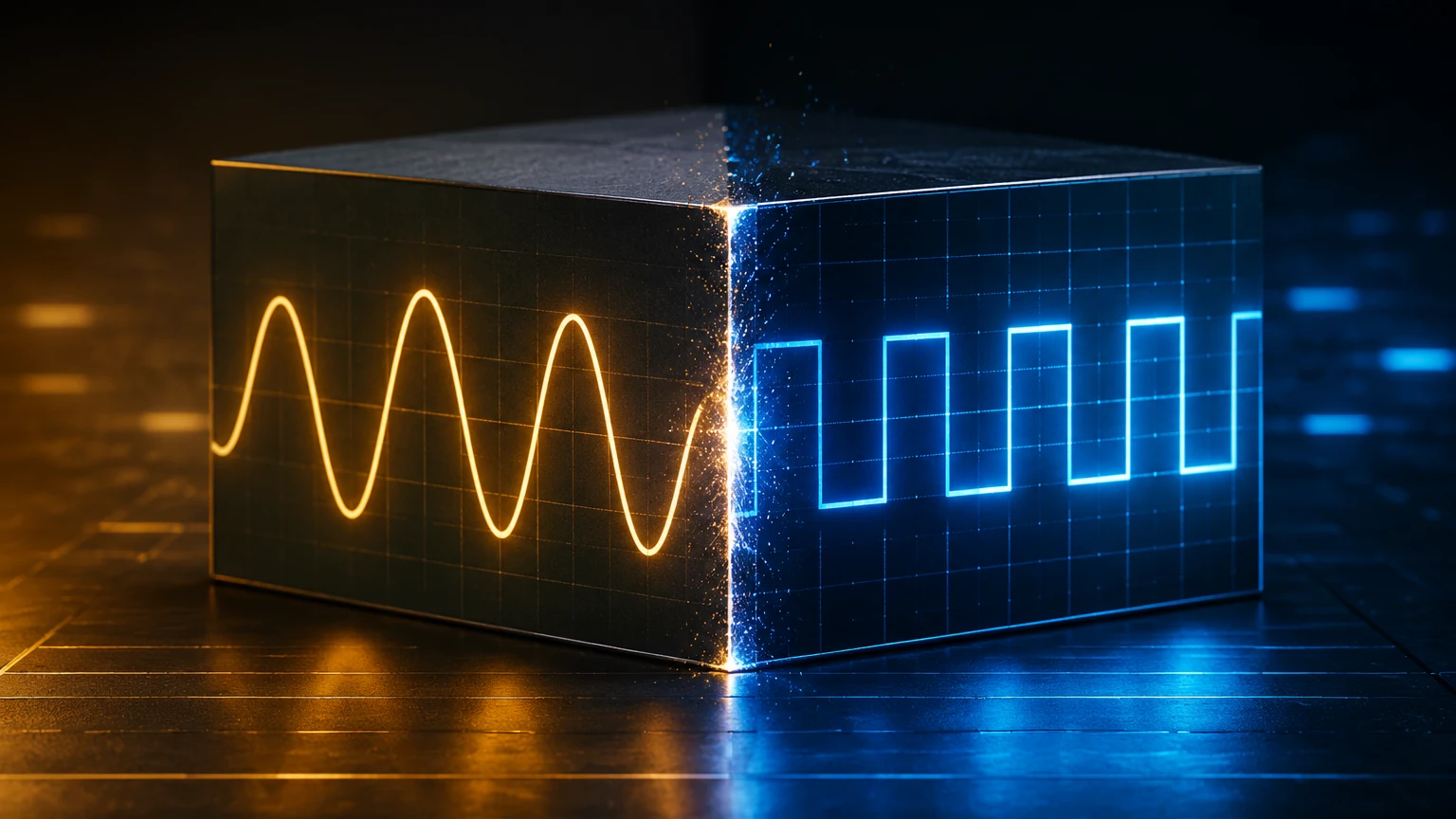
Analogue PD testing has been the industry standard for decades. These systems rely on analogue circuitry to amplify and display the discharge signals on an oscilloscope or a dedicated analogue meter.
Operational Mechanism
In an analogue system, the signal from the coupling capacitor is filtered and amplified through hardware components. The output is a real-time visual representation of the pulses. Operators must manually observe the "elliptical display" on a cathode-ray tube (CRT) or similar screen to interpret the magnitude and phase of the discharges.
Advantages and Limitations
* Advantages: Analogue systems provide a true real-time response without the latency introduced by digital processing. For experienced technicians, the raw signal can sometimes reveal subtle characteristics that might be smoothed over by digital filters.
* Limitations: The primary drawback of analogue testing is the lack of data storage and automated analysis. Interpreting results is highly subjective and depends on the skill of the operator. Furthermore, analogue systems have limited noise rejection capabilities, making them difficult to use in electrically "noisy" industrial environments where level meters often operate.
Digital PD Testing: Modern Advancements
As industrial environments become more complex, the shift toward digital vs analogue pd testing has accelerated. Digital PD systems utilize high-speed Analogue-to-Digital Converters (ADC) and Digital Signal Processing (DSP) to analyze discharge events.
The Digital Advantage
Digital systems convert the raw analogue signal into a stream of data. This allows for advanced mathematical modeling and noise suppression techniques that are impossible with analogue hardware. One of the most significant features of digital testing is Phase Resolved Partial Discharge (PRPD) analysis. This creates a 3D map of discharge activity, plotting pulse magnitude and frequency against the phase angle of the AC cycle.
Key Benefits
1. Noise Discrimination: Digital filters can distinguish between actual internal discharges and external interference from nearby motors or power lines.
2. Data Logging: Results can be stored, exported, and compared over time to identify trends in insulation degradation.
3. Automated Reporting: Modern systems provide automated pass/fail assessments based on pre-defined industrial standards.
Comparative Analysis: Digital vs Analogue PD Testing
For engineers selecting a testing methodology for their facility’s instrumentation infrastructure, the following table summarizes the key differences:
| Feature | Analogue PD Testing | Digital PD Testing |
| :— | :— | :— |
| Signal Processing | Hardware-based (Filters/Amplifiers) | Software-based (DSP/Algorithms) |
| Data Visualization | Real-time Oscilloscope (Elliptical) | PRPD Patterns, Histograms, 3D Plots |
| Noise Rejection | Basic (Fixed Frequency Filters) | Advanced (Dynamic Gating and Filtering) |
| Record Keeping | Manual (Notes/Photos) | Automatic Digital Storage and Trending |
| User Requirement | High Expertise Required for Interpretation | User-friendly with Automated Diagnostics |
| Accuracy | Subjective to Operator | Objective and Quantifiable |
Impact on Level Measurement Instrumentation
The choice between digital vs analogue pd testing directly impacts the reliability of level measurement systems. Instruments like radar level meters and ultrasonic transmitters are often installed in locations where electrical surges or harsh environmental conditions are common.
For instance, a high-frequency radar level meter relies on precise timing and signal integrity. If the internal insulation of the device's power module begins to fail due to partial discharge, the resulting electrical noise can interfere with the sensor's ability to detect the liquid surface accurately. By utilizing digital PD testing during routine maintenance of the plant's electrical distribution, engineers can ensure that the power supplied to these critical sensors is clean and that the devices themselves are protected from premature failure.
When reviewing your facility's instrumentation needs, it is helpful to Review product options and application support to see how modern digital interfaces in level meters complement advanced diagnostic testing protocols.
Selection and Installation Considerations
When implementing a PD testing program for industrial automation systems, consider the following factors:
1. Environmental Noise
If your facility has large Variable Frequency Drives (VFDs) or heavy machinery, digital PD testing is almost mandatory. The ability of digital systems to filter out pulse-width modulation (PWM) noise is essential for getting an accurate reading.
2. Sensitivity Requirements
For sensitive electronics in level transmitters, look for systems capable of detecting discharges as low as 1 pC to 5 pC. Digital systems generally offer higher sensitivity in practical field conditions due to their superior signal-to-noise ratios.
3. Sensor Integration
Ensure that the PD testing equipment is compatible with the coupling sensors used in your switchgear or transformer cabinets. In many modern water treatment or chemical processing plants, permanent PD sensors are installed to allow for continuous digital monitoring.
Limitations and Practical Challenges
While digital systems are superior in most B2B industrial applications, they are not without challenges. The complexity of digital software requires periodic updates and cybersecurity considerations. Additionally, the initial capital expenditure for a high-end digital PD analyzer is significantly higher than for basic analogue equipment. However, the reduction in unplanned downtime and the ability to perform predictive maintenance usually result in a lower Total Cost of Ownership (TCO).
Frequently Asked Questions (FAQs)
Q: Can digital PD testing replace all analogue methods?
A: In most industrial applications, yes. Digital systems provide more data and better noise rejection. However, some laboratory standards still reference analogue visualization for specific calibration procedures.
Q: How often should PD testing be performed on instrumentation power systems?
A: For critical level measurement applications in oil and gas or chemical processing, annual testing is recommended. If the environment is particularly harsh (high humidity or temperature fluctuations), semi-annual testing may be appropriate.
Q: Does PD testing damage the level meters?
A: No. PD testing is a non-destructive diagnostic method. It measures existing discharges at operating voltages (or slightly above) without causing further harm to the insulation, provided it is performed by trained personnel according to standard safety protocols.
Q: Is digital PD testing compatible with both AC and DC systems?
A: While most PD testing is focused on AC systems (due to the phase-related nature of the discharges), specialized digital systems are available for DC insulation testing, which is becoming more relevant in solar-powered remote level monitoring stations.
Conclusion
In the debate of digital vs analogue pd testing, the industry is clearly moving toward digital solutions. The ability to filter noise, log data, and perform complex pattern recognition makes digital testing the superior choice for maintaining the sophisticated electronics found in modern level measurement instruments. By integrating these advanced diagnostic techniques into a broader maintenance strategy, plant operators can ensure the continuous, accurate performance of their radar, ultrasonic, and hydrostatic level sensors, ultimately protecting both their assets and their bottom line.
For those seeking to upgrade their measurement capabilities, exploring the Main Page of a professional manufacturer can provide insights into how modern level meters are designed to withstand the electrical rigors of industrial environments.