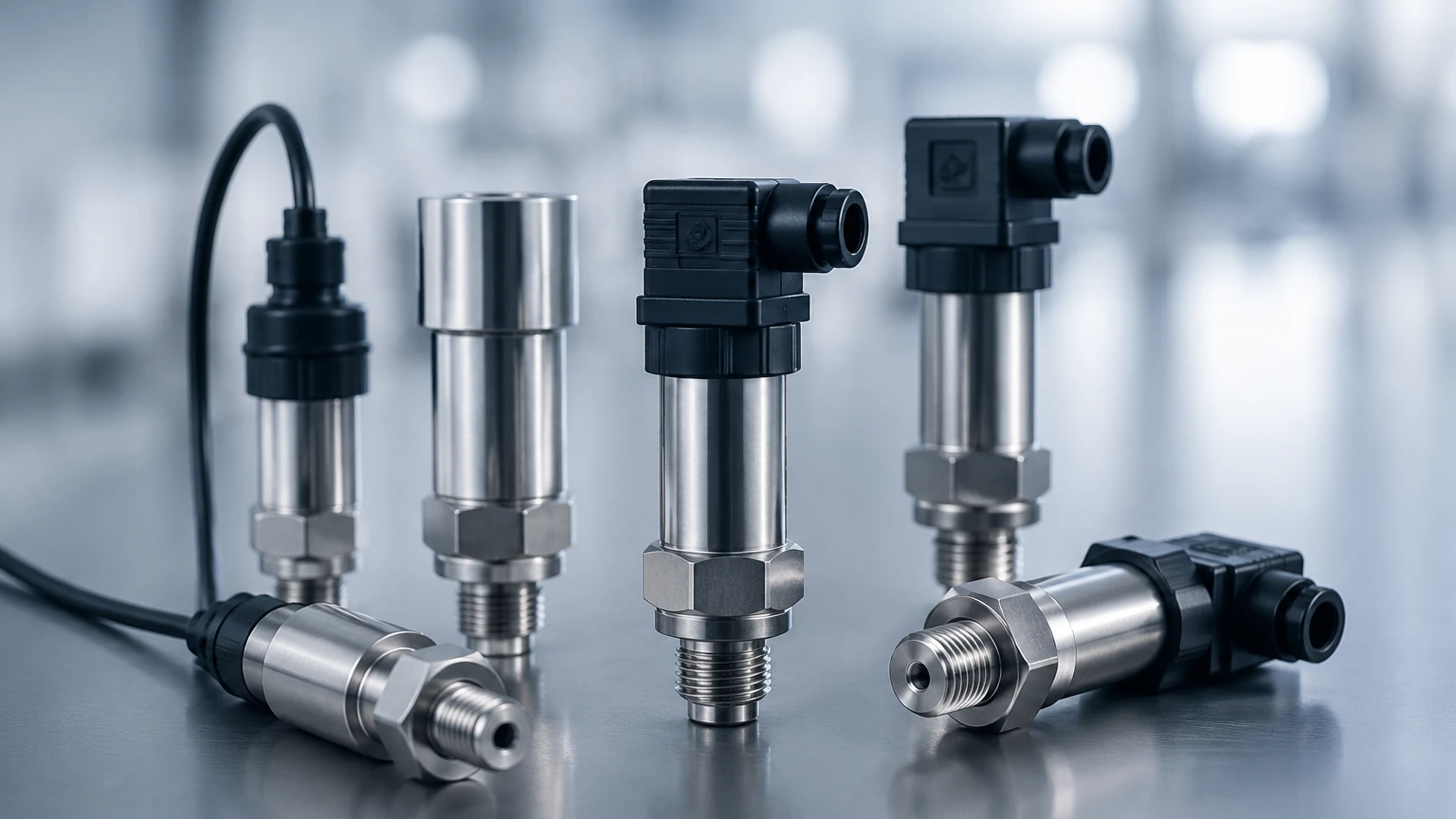
Pressure Sensors and Transducers
Pressure Sensors and Transducers
In the landscape of industrial automation and process control, the ability to quantify physical force is fundamental. Pressure sensors and transducers serve as the primary interface between mechanical process variables and electronic control systems. These devices are critical in applications ranging from simple hydraulic monitoring to complex hydrostatic level measurement in deep-well tanks. Understanding the underlying physics, signal conversion methods, and selection criteria is essential for engineers tasked with maintaining system integrity and measurement accuracy.
Fundamental Measurement Principles
Before selecting hardware, it is necessary to understand how pressure sensors and transducers convert mechanical stress into a measurable electrical signal. While various technologies exist, three primary principles dominate the industrial market.
Piezoresistive Sensors
This is the most common technology used in industrial pressure measurement. It utilizes the piezoresistive effect, where the electrical resistance of a semiconductor (typically silicon) or a metal strain gauge changes when subjected to mechanical strain. In a typical configuration, four strain gauges are bonded to a flexible diaphragm in a Wheatstone bridge circuit. When pressure deforms the diaphragm, the resulting change in resistance creates a proportional voltage output. These sensors are valued for their high sensitivity and robustness in general-purpose applications.
Capacitive Sensors
Capacitive pressure transducers measure changes in electrical capacitance caused by the movement of a diaphragm. The sensor consists of two conductive plates: one stationary and one flexible (the diaphragm). As pressure is applied, the diaphragm moves, changing the gap between the plates and, consequently, the capacitance. This technology is highly sensitive and is often preferred for low-pressure ranges or applications requiring high stability over time. Because there is no direct contact between the sensing element and the electronics, they offer excellent resistance to overpressure.
Resonant Wire and Optical Sensors
In specialized high-precision environments, resonant wire sensors may be used, where pressure changes the tension of a wire, altering its resonant frequency. Alternatively, optical sensors use fiber optics to detect diaphragm displacement, providing total immunity to electromagnetic interference (EMI), which is critical in high-voltage environments or areas with significant electrical noise.
Defining Sensors, Transducers, and Transmitters
In technical discourse, the terms "sensor," "transducer," and "transmitter" are often used interchangeably, but they represent different stages of signal processing:
1. Pressure Sensor: The basic element (e.g., the strain gauge) that experiences the physical change. It provides a raw, unconditioned electrical output (usually in millivolts).
2. Pressure Transducer: An integrated assembly that includes the sensor and basic signal conditioning circuitry. It typically outputs a higher-level voltage signal, such as 0–5V or 0–10V.
3. Pressure Transmitter: A more advanced device designed for industrial environments. It converts the transducer signal into a standardized current loop (typically 4–20mA) or a digital protocol like HART or RS485. Transmitters are designed for long-distance signal transmission with minimal interference.
For most B2B industrial applications, including those found on the Main Page of instrumentation catalogs, "transmitter" is the standard hardware format due to its reliability in noisy plant environments.
Pressure Reference Types
Selecting the correct reference point is vital for accuracy. Pressure is always measured relative to a reference:
* Gauge Pressure (psig / bar g): Measured relative to the local atmospheric pressure. This is the most common type for tank levels and pipe pressures.
* Absolute Pressure (psia / bar a): Measured relative to a perfect vacuum. This is used in vacuum distillation or meteorological applications where atmospheric fluctuations must be excluded.
* Differential Pressure (psid / bar d): Measures the difference between two pressure points. This is the basis for flow measurement (across an orifice plate) and pressurized tank level measurement.
Application in Hydrostatic Level Measurement
One of the most frequent uses for pressure sensors and transducers is determining the level of liquids in tanks. This is based on the hydrostatic principle: the pressure at the bottom of a liquid column is directly proportional to the height of the liquid and its density.
The formula used is:
P = ρ × g × h
Where:
* P = Hydrostatic pressure (Pa or bar)
* ρ (rho) = Density of the liquid (kg/m³)
* g = Gravity (approx. 9.81 m/s²)
* h = Height of the liquid (m)
In an open tank, a gauge pressure transmitter is mounted at the bottom. In a closed, pressurized tank, a differential pressure (DP) transmitter is required to subtract the overhead gas pressure from the total pressure at the bottom to isolate the liquid level.
Selection Table for Industrial Pressure Instruments
| Technology | Typical Range | Best For | Limitations |
| :— | :— | :— | :— |
| Piezoresistive (Silicon) | 0.1 bar to 1000 bar | General hydraulics, oil & gas, water distribution | Sensitive to temperature fluctuations without compensation |
| Ceramic (Capacitive) | 0.05 bar to 100 bar | Corrosive chemicals, food & beverage, wastewater | Lower pressure limits than metal diaphragms |
| Thin Film (Metal) | 5 bar to 2000 bar | High-pressure hydraulics, heavy machinery | Less sensitive at very low pressures |
| Hydrostatic Submersible | 0.1 bar to 20 bar | Deep wells, reservoirs, lift stations | Requires vented cable for atmospheric compensation |
Installation Considerations
Proper installation is as important as selecting the right sensor. Failure to follow engineering best practices often leads to signal drift or premature device failure.
1. Mounting Position: For gas applications, the sensor should be mounted above the process line to allow moisture to drain away. For liquid applications, it should be mounted below or level with the line to prevent gas bubbles from entering the sensor chamber.
2. Impulse Piping: If the sensor is not direct-mounted, impulse lines should be as short as possible. For high-temperature media, a siphon or cooling tower must be used to protect the sensing diaphragm from exceeding its rated temperature (typically 85°C to 120°C for standard units).
3. Environmental Protection: In outdoor or wash-down environments, ensure the housing meets IP67 or IP68 standards. For hazardous areas (explosive dust or gas), specify intrinsically safe (Ex ia) or explosion-proof (Ex d) ratings.
4. Venting: Gauge pressure sensors require a vent to the atmosphere. In submersible models, this is achieved via a small tube inside the signal cable. If this tube becomes blocked or kinked, the reading will drift as local barometric pressure changes.
Limitations and Common Risks
While pressure sensors and transducers are highly reliable, certain factors can compromise their performance:
* Temperature Drift: All sensors exhibit some change in output with temperature. High-quality transmitters include internal temperature compensation, but extreme process temperatures can still cause errors.
* Overpressure and Spikes: Water hammer or rapid valve closures can create pressure spikes far exceeding the sensor's burst pressure. Using snubbers or selecting a sensor with a high overpressure rating (e.g., 4x the nominal range) can mitigate this risk.
* Chemical Compatibility: The wetted parts (diaphragm and process connection) must be compatible with the media. While 316L stainless steel is standard, aggressive media like chlorine or strong acids may require Hastelloy, Monel, or ceramic diaphragms.
* Long-term Drift: Over years of service, the elastic properties of the diaphragm may change slightly. Periodic calibration (typically annually) is recommended to maintain accuracy.
Frequently Asked Questions (FAQs)
Q: What is the difference between a 2-wire and a 3-wire transducer?
A: A 2-wire transmitter uses the same two wires for both power supply and the 4-20mA output signal, making it ideal for long-distance wiring. A 3-wire transducer uses two wires for power (V+ and Ground) and a third wire for the voltage output signal (e.g., 0-10V).
Q: Can I use a pressure sensor to measure the weight of a tank?
A: Yes, this is known as gravimetric leveling. By measuring the pressure at the bottom and knowing the surface area of the tank, the total weight can be calculated, provided the liquid density is constant.
Q: How do I handle media that might clog the sensor?
A: For viscous fluids, sludges, or media with solids, use a "flush diaphragm" transmitter. Unlike standard sensors with a small pressure port, flush diaphragms have a flat sensing surface that prevents material buildup.
Q: Why is my sensor reading non-zero when the tank is empty?
A: This is often due to a mounting offset or zero-point drift. Most modern transmitters allow for a "zero trim" function to reset the baseline after installation.
Conclusion
Pressure sensors and transducers are the backbone of modern process monitoring. Whether the goal is to manage hydraulic force, monitor steam lines, or track inventory via hydrostatic level measurement, selecting the correct technology requires a balance of accuracy requirements, environmental constraints, and budget. For engineers and procurement professionals, confirming wetted material compatibility and signal output standards early in the project phase prevents costly integration issues later. By adhering to established installation guidelines and understanding the limitations of each sensing principle, industrial operators can ensure long-term reliability and safety in their automation systems.