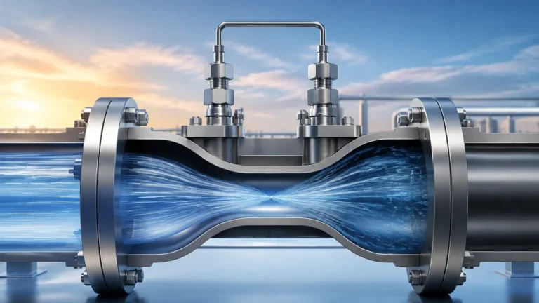
Static Pressure Monitoring System
Static Pressure Monitoring System
In industrial process control, a static pressure monitoring system is a fundamental tool for determining the level, volume, and mass of liquids within storage tanks and processing vessels. By leveraging the physical relationship between the height of a liquid column and the pressure it exerts at a specific depth, engineers can achieve reliable and continuous monitoring without the complexities of moving parts. This technology, often referred to as hydrostatic level measurement, is a staple in water treatment, chemical processing, and the oil and gas industry due to its robustness and cost-effectiveness.
Understanding the engineering principles behind these systems is essential for selecting the correct instrumentation and ensuring long-term accuracy. This guide explores the mechanical foundations, selection criteria, and installation best practices for implementing an effective static pressure monitoring system.
Measurement Principles of Static Pressure Systems
The operation of a static pressure monitoring system is based on the principle of hydrostatics. Hydrostatic pressure is the pressure exerted by a fluid at equilibrium at a given point within the fluid, due to the force of gravity. In a stationary liquid, the pressure increases in direct proportion to the depth because of the increasing weight of the fluid above.
The Hydrostatic Equation
The relationship is defined by the following formula:
P = ρ × g × h
Where:
* P is the hydrostatic pressure (measured in Pascals or bar).
* ρ (rho) is the density of the liquid (kg/m³).
* g is the local acceleration due to gravity (approximately 9.81 m/s²).
* h is the height of the liquid column above the sensor (meters).
In most industrial applications, gravity is considered a constant. Therefore, if the density of the liquid is known and remains stable, the pressure measured by the sensor is directly proportional to the height of the liquid. A static pressure monitoring system measures this pressure and converts it into an electronic signal (such as 4-20mA or a digital protocol) that represents the level.
Gauge vs. Absolute Pressure
Most systems use gauge pressure sensors, which measure the pressure relative to atmospheric pressure. This is critical because the surface of a liquid in an open tank is also subject to atmospheric pressure. By using a vented sensor or a differential pressure transmitter, the system "cancels out" the atmospheric pressure, ensuring that only the pressure exerted by the liquid column is measured.
Core Components of the System
A complete static pressure monitoring system typically consists of three primary elements:
1. The Pressure Transducer/Sensor: This component contains a diaphragm that deforms under the weight of the liquid. The deformation is measured by sensing elements (such as piezoresistive or ceramic thick-film sensors) and converted into an electrical signal.
2. The Transmitter/Signal Conditioner: This circuitry stabilizes the raw signal from the sensor, compensates for temperature fluctuations, and scales the output to a standard industrial format like 4-20mA, HART, or Modbus.
3. The Monitoring Interface: This can be a local digital display, a Programmable Logic Controller (PLC), or a Distributed Control System (DCS) that interprets the signal and provides data for process control or inventory management.
For those seeking specific hardware configurations and technical data sheets, reviewing the Main Page of a professional manufacturer like Welk provides a comprehensive look at the various sensor architectures available for different industrial environments.
Key Evaluation Criteria for Sensor Selection
Selecting the right sensor for a static pressure monitoring system requires a thorough analysis of the process environment. Failure to account for chemical compatibility or pressure ranges can lead to premature sensor failure or inaccurate readings.
Media Density and Consistency
Since the system relies on density to calculate height, any change in the liquid's density will result in a measurement error. For example, if a tank is used for different chemicals with varying densities, the system must be recalibrated for each fluid. If the media is prone to stratification or contains high solids, the sensor diaphragm must be protected from clogging.
Chemical Compatibility
The wetted parts of the sensor—including the diaphragm and the housing—must be resistant to the process media. Standard 316L stainless steel is suitable for water and many oils, but corrosive chemicals may require Hastelloy, Monel, or specialized coatings like PTFE.
Pressure Range and Overpressure Protection
The sensor's calibrated range should closely match the maximum height of the tank to ensure the highest resolution. Additionally, the sensor must be able to withstand potential pressure surges (water hammer) or accidental overfilling without permanent damage to the diaphragm.
Selection Table: Submersible vs. External Mounting
Choosing between a submersible sensor and an externally mounted transmitter depends largely on tank accessibility and the nature of the liquid.
| Feature | Submersible Pressure Transmitter | External/Flanged Pressure Transmitter |
| :— | :— | :— |
| Mounting Location | Suspended from the top into the liquid | Mounted to a nozzle at the bottom/side |
| Best Use Case | Deep wells, reservoirs, open sumps | Process tanks, pressurized vessels |
| Installation Ease | High (no tank penetration required at bottom) | Moderate (requires a flange or threaded port) |
| Maintenance | Easy to pull up via cable | May require draining the tank or isolation valves |
| Atmospheric Venting | Via a capillary tube in the cable | Via a vent port on the transmitter housing |
| Media Constraints | Not ideal for high-turbulence or high-temp | Suitable for high-temp with cooling siphons |

Installation Considerations and Best Practices
Proper installation is the most critical factor in the reliability of a static pressure monitoring system. Even the most accurate sensor will provide poor data if it is installed incorrectly.
Atmospheric Pressure Compensation
For sensors used in open tanks, the back of the diaphragm must be exposed to atmospheric pressure. In submersible sensors, this is achieved through a small vent tube (capillary) inside the cable. It is vital to ensure this tube is not kinked, blocked, or exposed to moisture. Many engineers use a desiccant cartridge at the end of the vent tube to prevent condensation inside the sensor.
Avoiding Turbulence and Mechanical Stress
Sensors should not be placed directly in the path of an inlet flow or near an agitator. The kinetic energy of moving fluid can create localized pressure changes that the sensor interprets as level fluctuations. If turbulence is unavoidable, the sensor should be installed inside a stilling well (a perforated pipe) to dampen the fluid movement.
Positioning in the Tank
The sensor should be mounted slightly above the bottom of the tank (typically 100mm to 300mm) to prevent it from being buried in sediment or sludge. If the sensor must measure to the very bottom, a flush-diaphragm model should be used to minimize the risk of clogging.
Cabling and Electrical Protection
In submersible applications, the cable provides both the electrical connection and the physical support. It should be securely anchored to prevent the sensor from drifting. Furthermore, in outdoor installations, surge protection is recommended to protect the transmitter from lightning strikes and electrical transients.
Common Risks and Limitations
While a static pressure monitoring system is highly reliable, it is not a "fit and forget" solution for every application. Engineers must be aware of the following limitations:
* Density Sensitivity: As mentioned, the system measures weight, not actual distance. If the temperature of the liquid changes significantly, its density will change, leading to a level error. For high-precision applications, temperature compensation or a multi-parameter sensor may be required.
* Pressurized Tanks: In a closed, pressurized vessel, the pressure above the liquid adds to the hydrostatic pressure at the bottom. A standard gauge pressure sensor cannot distinguish between the two. In these cases, a differential pressure (DP) transmitter must be used, with one side measuring the bottom pressure and the other measuring the headspace pressure.
* Sediment and Coating: If the liquid is prone to crystallization or contains heavy solids, the diaphragm may become coated. This increases the stiffness of the diaphragm and causes measurement drift. Regular cleaning or the use of non-clogging flush diaphragms is necessary in these environments.
Frequently Asked Questions (FAQs)
1. Can a static pressure monitoring system be used for boiling liquids?
It is generally not recommended for boiling liquids because the density of the liquid is highly unstable and the presence of gas bubbles (void fraction) significantly reduces the effective density, leading to under-reading of the level. Non-contact methods like radar are often preferred for boiling applications.
2. How often should the system be calibrated?
In clean water applications, annual calibration is usually sufficient. However, in corrosive or high-temperature environments, semi-annual checks are recommended to account for potential sensor drift or diaphragm fatigue.
3. What is the maximum depth a submersible sensor can measure?
Welk and other professional manufacturers offer sensors capable of measuring depths up to 200 meters or more. The limiting factor is usually the tensile strength of the cable and the pressure range of the sensing element.
4. Does the shape of the tank affect the pressure reading?
No. Hydrostatic pressure depends only on the vertical height of the liquid and its density. Whether the tank is narrow, wide, or irregularly shaped, the pressure at a specific depth remains the same. However, tank shape is critical when converting that level measurement into a volume calculation.
5. Why is my sensor reading higher than the actual level?
This is often caused by a blocked vent tube. If the atmospheric pressure increases and the vent tube is blocked, the sensor cannot compensate, leading to an offset in the reading. Another possibility is that the liquid density has increased (e.g., due to higher salt concentration or lower temperature).
Conclusion
A static pressure monitoring system offers a balance of simplicity and precision that is difficult to match with other technologies. By understanding the underlying physics and carefully selecting components based on chemical compatibility and installation requirements, process engineers can implement a solution that provides years of accurate data. For those in the planning stages of a project, consulting technical resources on the Main Page of an established manufacturer can help bridge the gap between theoretical design and practical application, ensuring the selected instrumentation meets the specific demands of the industrial environment.