Gas Ultrasonic Flow Meter
Gas Ultrasonic Flow Meter
In the landscape of industrial automation and process control, the gas ultrasonic flow meter has emerged as a cornerstone technology for high-accuracy measurement. Unlike traditional mechanical meters that rely on moving parts, ultrasonic technology utilizes acoustic signals to determine the velocity of a gas moving through a pipe. This non-intrusive approach offers significant advantages in terms of maintenance, pressure drop, and long-term reliability. For engineers and facility managers, understanding the nuances of these instruments is essential for optimizing gas custody transfer, flare gas monitoring, and industrial process efficiency.
As a professional manufacturer of industrial measurement instruments, Welk provides a range of solutions that integrate seamlessly with broader process monitoring systems. Whether managing storage tank levels or monitoring the throughput of gaseous media, selecting the right instrumentation requires a deep dive into the physics of the measurement and the specific constraints of the application environment.
Understanding the Measurement Principle
Before selecting a gas ultrasonic flow meter, it is vital to understand the underlying physics that govern its operation. The vast majority of industrial gas ultrasonic meters utilize the Transit-Time (Time-of-Flight) principle.
Transit-Time Principle
In this method, pairs of ultrasonic transducers are mounted on the pipe. These transducers act as both transmitters and receivers. They send ultrasonic pulses back and forth across the pipe at an angle.
1. Downstream Pulse: A pulse traveling with the flow of the gas moves faster.
2. Upstream Pulse: A pulse traveling against the flow moves slower.
The difference in the time it takes for these pulses to travel the same distance is directly proportional to the velocity of the gas. The basic equation for flow velocity ($v$) can be expressed as:
$$v = \frac{L}{2 \cos \theta} \left( \frac{1}{t_{up}} – \frac{1}{t_{down}} \right)$$
Where:
* $L$ is the path length between transducers.
* $\theta$ is the angle of the ultrasonic path relative to the pipe axis.
* $t_{up}$ is the transit time in the upstream direction.
* $t_{down}$ is the transit time in the downstream direction.
Because the speed of sound in gas varies significantly with temperature, pressure, and gas composition, modern meters use multi-path configurations (often 2 to 18 paths) to calculate an average velocity profile across the entire cross-section of the pipe. This increases accuracy by compensating for non-ideal flow profiles.
The Role of Speed of Sound (SoS)
A unique feature of the gas ultrasonic flow meter is its ability to calculate the "Speed of Sound" in the medium. By comparing the measured SoS with theoretical values based on gas chromatography data, operators can verify the health of the meter and detect changes in gas composition or the presence of contaminants like liquids or solids.
Types of Gas Ultrasonic Flow Meters
Industrial gas ultrasonic meters are generally categorized by their mechanical design and the number of acoustic paths they employ.
Inline Flow Meters
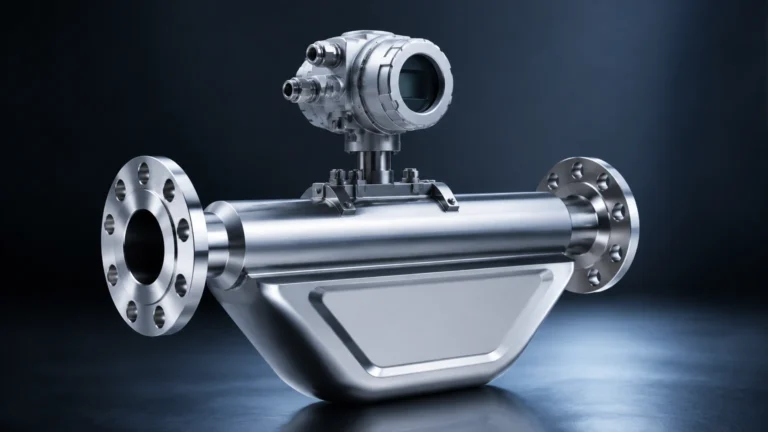
Inline meters consist of a manufactured spool piece that is flanged into the pipeline. The transducers are factory-aligned and calibrated. These are the gold standard for custody transfer and high-accuracy industrial applications because the geometry of the measurement path is fixed and precisely known. They are capable of handling high pressures, often exceeding 100 bar (1450 psi).
Clamp-On Flow Meters
Clamp-on ultrasonic meters use transducers strapped to the outside of the pipe. While more common for liquid applications, high-power gas clamp-on meters are used for temporary measurements or in systems where the process cannot be shut down for installation. However, they generally offer lower accuracy than inline models due to signal attenuation through the pipe wall and uncertainties in pipe wall thickness.
Multi-Path vs. Single-Path
* Single-Path: Suitable for basic process control where high precision is not required. They are sensitive to flow profile distortions.
* Multi-Path: Essential for custody transfer. By measuring velocity at different chords of the pipe, they can mathematically correct for swirl and asymmetry in the flow.
Key Evaluation Criteria for Industrial Selection
Selecting a gas ultrasonic flow meter involves more than just matching pipe sizes. Engineers must evaluate the following criteria to ensure long-term performance:
1. Gas Composition: The meter must be calibrated for the specific gas type (e.g., natural gas, nitrogen, CO2, or flare gas). High concentrations of CO2 or heavy hydrocarbons can attenuate ultrasonic signals, requiring higher-power transducers.
2. Pressure and Temperature: Gas density changes with pressure. Most ultrasonic meters require a minimum operating pressure (often >1 bar or 14.5 psi) to ensure sufficient acoustic coupling between the gas and the transducer.
3. Rangeability (Turndown Ratio): One of the greatest strengths of ultrasonic technology is its high turndown ratio, often exceeding 100:1. This allows the meter to measure very low leak rates and very high peak flows accurately.
4. Accuracy Requirements: For custody transfer, accuracies of ±0.5% or better are required. For general process monitoring, ±1.0% to ±2.0% is often sufficient.
Practical Selection and Specification Table
The following table provides a general guideline for selecting a gas ultrasonic flow meter based on typical industrial pipe sizes and flow conditions.
| Pipe Size (DN) | Pipe Size (Inches) | Velocity Range (m/s) | Typical Accuracy | Application Type |
| :— | :— | :— | :— | :— |
| 50 – 100 mm | 2" – 4" | 0.3 – 30 m/s | ±1.0% | Industrial Gas Distribution |
| 150 – 300 mm | 6" – 12" | 0.1 – 35 m/s | ±0.5% | Custody Transfer / City Gates |
| 400 – 1000 mm | 16" – 40" | 0.1 – 40 m/s | ±0.5% | Main Transmission Lines |
| Variable | Variable | 0.01 – 80 m/s | ±2.0% – 5.0% | Flare Gas / Waste Gas |
*Note: Flow velocities are typically measured in meters per second (m/s). For imperial reference, 1 m/s is approximately 3.28 ft/s.*
Installation Guidelines and Flow Conditioning
Even the most advanced gas ultrasonic flow meter will fail to provide accurate data if installed incorrectly. The goal of installation is to ensure a "fully developed" and symmetrical flow profile reaches the measurement paths.
Straight Pipe Requirements
Standard installations typically require a minimum of 10 diameters (10D) of straight pipe upstream of the meter and 5 diameters (5D) downstream. If there are high-disturbance elements like double elbows out of plane or pressure-regulating valves, these requirements may increase to 20D or more.
Flow Conditioners
In space-constrained environments, a flow conditioner (such as a perforated plate) can be installed upstream. This device breaks up large-scale turbulence and swirl, allowing for a shorter upstream straight run (often reduced to 5D).
Transducer Orientation
For gas applications, transducers should ideally be mounted in the horizontal plane (3 o'clock and 9 o'clock positions). This prevents the accumulation of liquids (condensate) or solids (dust/scale) on the transducer faces, which could dampen or block the ultrasonic signal.
Limitations and Operational Risks
While highly versatile, the gas ultrasonic flow meter has specific limitations that must be managed:
* Acoustic Noise: Pressure-reducing valves located near the meter can generate high-frequency ultrasonic noise that interferes with the meter’s signals. Specialized "noise-reduction" transducers or increased distance from the valve may be necessary.
* Liquid Entrainment: While these meters can handle small amounts of mist, significant liquid slugs will block the ultrasonic path entirely, leading to a "signal loss" error.
* Minimum Pressure: At very low pressures or vacuum conditions, the gas molecules are too sparse to effectively transmit ultrasonic energy. Most standard meters are not suitable for near-vacuum applications.
* Initial Cost: The upfront investment for a high-quality multi-path gas ultrasonic meter is higher than for a vortex or turbine meter. However, the total cost of ownership is often lower due to reduced maintenance and zero pressure drop.
For comprehensive system integration, including how flow measurement pairs with tank level monitoring, you can Review product options and application support on our Main Page.
Frequently Asked Questions (FAQs)
Q: Can a gas ultrasonic flow meter measure steam?
A: Yes, but it requires specialized high-temperature transducers and a design that can handle the specific acoustic properties of steam. Standard gas meters are usually rated for temperatures up to 80°C or 100°C (176°F – 212°F), whereas steam requires much higher ratings.
Q: Does gas composition change the accuracy?
A: Yes. Because the speed of sound changes with the molecular weight of the gas, the meter must be programmed with the correct gas composition (e.g., % Methane, % Ethane, etc.) to perform internal diagnostic checks, though the transit-time measurement itself is largely independent of the speed of sound.
Q: How often do these meters need calibration?
A: In non-custody transfer applications, these meters often run for 5 to 10 years without a shift in calibration because there are no moving parts to wear out. For custody transfer, local regulations usually dictate a recalibration interval of 2 to 5 years.
Q: What happens if the transducers get dirty?
A: Most modern meters have a "signal strength" diagnostic. As dirt builds up, the signal strength will drop. The meter will continue to work accurately until the signal falls below a certain threshold, at which point an alarm is triggered, indicating that the transducers need cleaning.
Conclusion
The gas ultrasonic flow meter represents a significant leap forward in process transparency. By providing high-accuracy data with minimal maintenance, it allows industrial operators to manage resources more effectively. When integrated into a complete measurement strategy—alongside reliable radar or ultrasonic level sensors—it ensures that every cubic meter of gas is accounted for from storage to end-use.
When planning your next installation, always confirm the minimum operating pressure, the expected gas composition, and the available straight-pipe run. For further technical specifications and to explore our full range of industrial measurement instruments, visit our Main Page.