Rheonik Coriolis Sensors
Rheonik Coriolis Sensors
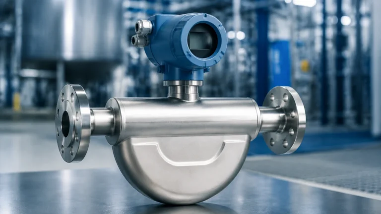
In the landscape of industrial process control, the ability to measure mass flow, density, and temperature simultaneously with a single instrument provides a significant advantage. Rheonik Coriolis sensors have established a specialized niche within this field, particularly for applications involving extreme pressures, high temperatures, and low flow rates. Unlike traditional volumetric flow meters, these sensors measure mass directly, making them immune to changes in fluid properties such as viscosity, conductivity, and pressure.
For engineers and procurement specialists focused on integrated level and flow solutions, understanding the mechanical principles and application boundaries of Rheonik technology is essential. While level measurement instruments—such as those available on the Main Page—provide critical data on the volume and surface position of liquids in a vessel, Coriolis sensors provide the mass-balance data necessary to verify inventory accuracy and process efficiency.
Measurement Principles of Coriolis Technology
The operation of a Coriolis meter is rooted in the physics of motion, specifically the Coriolis effect. To understand how Rheonik Coriolis sensors function, one must first visualize the internal geometry of the sensor, which typically consists of one or two measuring tubes.
The Coriolis Effect in Flow Tubes
An internal electromagnetic drive coil causes the measuring tubes to vibrate at their resonant frequency. When there is no flow, the tubes vibrate in a uniform, symmetrical manner. However, when a fluid (liquid or gas) flows through these vibrating tubes, it is subjected to a Coriolis force. This force acts perpendicular to both the direction of the flow and the axis of the vibration.
According to Newton's Second Law of Motion ($F=ma$), the fluid resists the vibration. On the inlet side of the sensor, the fluid resists being pushed upward, while on the outlet side, the fluid resists being pushed downward. This creates a twisting motion or a "phase shift" in the tube's vibration. The magnitude of this phase shift is directly proportional to the mass flow rate of the fluid.
Density and Temperature Measurement
Beyond mass flow, Rheonik sensors utilize the frequency of the vibration to determine the fluid's density. A denser fluid increases the mass of the vibrating system, thereby lowering the resonant frequency. By measuring this frequency shift, the sensor can calculate real-time density. Furthermore, because the elasticity of the metal tubes changes with temperature, a high-precision Pt100 temperature sensor is integrated into the meter to compensate for these changes, providing a third process variable: temperature.
The Rheonik Omega Tube Design
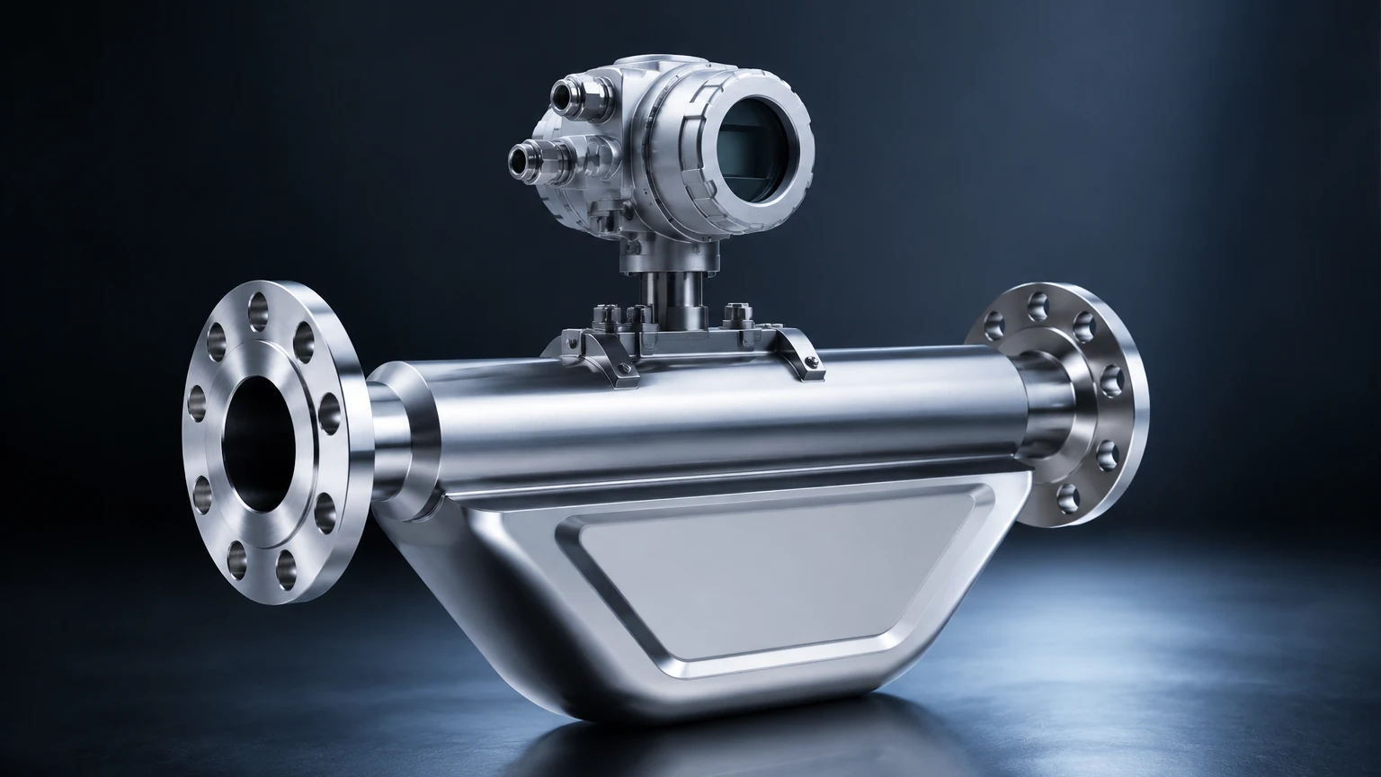
What distinguishes Rheonik from other Coriolis manufacturers is their signature "Omega" ($\Omega$) tube geometry. While many competitors use U-shaped or straight tubes, the Omega design offers specific mechanical advantages that are particularly relevant in heavy industrial environments.
High Pressure and Thick Wall Construction
In high-pressure applications, such as hydrogen refueling or offshore chemical injection, flow tubes must be thick-walled to ensure safety and longevity. In standard Coriolis designs, thick walls make the tubes too stiff to vibrate effectively, reducing sensitivity. The Rheonik Omega shape, combined with unique torsion rod technology, provides high mechanical leverage. This allows the sensor to maintain high accuracy and sensitivity even when using heavy-walled tubes capable of withstanding pressures exceeding 1,000 bar (14,500 psi).
Stress Distribution and Durability
The Omega shape naturally distributes mechanical stress more evenly across the tube than a U-shape. This reduces the risk of fatigue failure at the manifold joints. Additionally, the design allows for a larger tube diameter relative to the overall sensor footprint, which helps minimize pressure drop—a critical factor when dealing with high-viscosity fluids or gravity-fed systems.
Key Evaluation Criteria for Selection
Selecting the correct Rheonik Coriolis sensor requires an analysis of several process parameters. Engineers should evaluate the following criteria before finalizing a specification:
1. Mass Flow Range
Rheonik offers sensors ranging from the RHM 015 (designed for micro-flow applications as low as 0.002 kg/min) to the RHM 160 (capable of measuring up to 30,000 kg/min). It is vital to select a sensor where the typical operating flow falls within the "sweet spot" of the meter's accuracy curve, usually between 20% and 80% of its maximum rating.
2. Material Compatibility
The wetted parts must be compatible with the process fluid to prevent corrosion or erosion. Common materials include:
* 316L Stainless Steel: The standard for most water-based and chemical applications.
* Hastelloy C22: Used for highly corrosive media like acids and chlorides.
* Tantalum: Reserved for the most aggressive chemical environments.
* Super Duplex: Often used in oil and gas for its high strength and resistance to pitting.
3. Process Conditions (Temperature and Pressure)
Rheonik sensors are renowned for their ability to operate in cryogenic temperatures (down to -200°C / -328°F) and extreme heat (up to 350°C / 662°F). When selecting a sensor, always confirm the maximum allowable working pressure (MAWP) at the specific operating temperature, as the pressure rating of metals decreases as temperature rises.
Practical Selection Table
| Series | Typical Line Size | Max Flow Rate (kg/min) | Max Pressure (bar) | Primary Application |
| :— | :— | :— | :— | :— |
| RHM 015 to 08 | 1/4" to 1/2" | 0.6 to 50 | Up to 1000 | Chemical dosing, pilot plants, high-pressure gas |
| RHM 10 to 40 | 1" to 3" | 100 to 1,500 | Up to 450 | General process, food & beverage, oil loading |
| RHM 60 to 160 | 4" to 12" | 3,000 to 30,000 | Up to 350 | Bulk transport, custody transfer, large-scale production |
Installation Considerations and Best Practices
To achieve the high accuracy levels (often ±0.05% to ±0.1%) promised by Rheonik Coriolis sensors, proper installation is mandatory. Unlike ultrasonic or radar level meters, which are non-contact, Coriolis meters are inline devices that are sensitive to the mechanical environment.
Vibration Isolation
Because the sensor operates on the principle of vibration, external mechanical noise from pumps, motors, or vibrating pipes can interfere with the measurement. Sensors should be mounted using rigid supports on both the inlet and outlet sides. In some cases, flexible hosing may be required to decouple the meter from a vibrating manifold.
Orientation for Gas and Liquid
* For Liquids: The sensor should ideally be installed in a "tubes down" position (flag or belly down) to ensure the tubes remain full and to prevent gas bubbles from becoming trapped.
* For Gases: The sensor should be installed "tubes up" to allow any condensed liquids to drain out of the measuring tubes, preventing measurement errors caused by two-phase flow.
* Vertical Installation: This is often preferred as it allows for self-draining, provided the flow is moving upward to ensure the tubes stay primed.
Zero Point Calibration
After installation and once the meter is filled with the process fluid at operating temperature and pressure, a "Zero Calibration" must be performed. This procedure tells the transmitter what the sensor "sees" at zero flow. It is the most critical step in ensuring low-flow accuracy.
Integration with Level Measurement Systems
In many industrial setups, Coriolis sensors work in tandem with level measurement technology. For instance, in a chemical storage tank, a Welk radar level meter provides the volume of the liquid based on the surface height. However, if the chemical's density changes due to temperature fluctuations, the volume-to-mass calculation becomes inaccurate.
By integrating a Rheonik Coriolis sensor on the discharge line, operators can obtain the exact mass of the fluid leaving the tank. This data can be used to "cross-check" the level meter's readings. If the mass flow data and the level change data do not align, it may indicate a leak, a change in fluid concentration, or a buildup of foam or vapor that is affecting the level sensor. For comprehensive instrumentation options, engineers often consult the Main Page to select the appropriate level transmitter to complement their flow systems.
Common Risks and Limitations
While highly versatile, Rheonik Coriolis sensors are not a universal solution for every application. Understanding their limitations prevents costly misapplications.
* Entrained Gas (Slug Flow): Coriolis meters struggle when large pockets of gas are present in a liquid stream. This causes "damping" of the tube vibration, leading to high noise or measurement failure. While Rheonik's advanced electronics (like the RHE series transmitters) have algorithms to handle some entrained gas, it remains a challenge for accuracy.
* Pressure Drop: Because the fluid must be diverted through the measuring tubes, there is an inherent pressure drop across the meter. This must be calculated during the design phase to ensure the system has enough head pressure to maintain the required flow rate.
* Initial Cost: The capital expenditure for a Coriolis meter is significantly higher than for a magnetic or vortex flow meter. Its use is typically justified by the need for high accuracy, multi-variable data, or the ability to handle extreme process conditions.
Frequently Asked Questions (FAQs)
Q: Can Rheonik sensors measure the level of a tank directly?
A: No. Coriolis sensors measure mass flow and density within a pipe. To measure the level of a tank, you should use hydrostatic, ultrasonic, or radar level transmitters, such as those found on the Main Page. However, the density data from a Coriolis sensor can be used to improve the accuracy of hydrostatic level measurements.
Q: How often do Rheonik Coriolis sensors need recalibration?
A: Because there are no moving parts or bearings to wear out, the mechanical calibration of the tubes is extremely stable. Most industrial users recalibrate every 2 to 5 years, depending on the criticality of the process and local regulatory requirements (such as custody transfer laws).
Q: Are these sensors suitable for hygienic applications?
A: Yes, Rheonik produces versions with polished internal surfaces and Tri-Clamp connections that meet EHEDG and 3A standards for the food, beverage, and pharmaceutical industries.
Q: What is the maximum viscosity a Rheonik sensor can handle?
A: There is no theoretical limit to viscosity as long as the fluid can be pumped through the tubes. However, extremely viscous fluids will result in a very high pressure drop, which may require a larger sensor size than the pipe diameter would suggest.
Conclusion
Rheonik Coriolis sensors represent a pinnacle of flow measurement engineering, offering unmatched performance in high-pressure and high-temperature environments. By leveraging the unique Omega tube design and torsion rod technology, these sensors provide reliable mass flow and density data where other meters fail. When combined with robust level measurement strategies, they form the backbone of a precise and efficient industrial process control system.