Water Conductivity Probe
Water Conductivity Probe
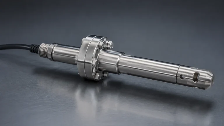
In industrial process control, the measurement of liquid properties is as critical as the measurement of volume or level. A water conductivity probe is a fundamental sensor used to determine the ability of an aqueous solution to carry an electrical current. This measurement serves as a direct proxy for the concentration of dissolved solids, ions, and impurities within the water. From monitoring the purity of deionized water in pharmaceutical manufacturing to controlling the chemical dosage in cooling towers, the conductivity probe is an indispensable tool for maintaining process efficiency and product quality.
Understanding the technical nuances of these sensors—ranging from electrode materials to measurement principles—is essential for engineers tasked with designing reliable automation systems. This guide explores the engineering principles, selection criteria, and installation best practices for water conductivity probes in B2B industrial environments.
Understanding Conductivity Measurement Principles
Conductivity is the reciprocal of electrical resistivity. In a liquid, electricity is conducted by the movement of ions. Therefore, as the concentration of dissolved salts, acids, or bases increases, the conductivity of the water also rises. The standard unit of measurement is Siemens per meter (S/m), though in industrial water treatment, it is more commonly expressed in microsiemens per centimeter (µS/cm) or millisiemens per centimeter (mS/cm).
The Role of the Cell Constant (K)
The geometry of the probe significantly influences the measurement. A water conductivity probe consists of two or more electrodes with a specific surface area (A) placed at a fixed distance (L) from each other. The ratio of the distance to the area (L/A) is known as the "Cell Constant" or "K-factor."
* Low K-factors (e.g., K=0.01 or 0.1): Used for high-purity water (low conductivity), where the electrodes are placed very close together or have a large surface area to capture a measurable signal.
* High K-factors (e.g., K=1.0 or 10.0): Used for wastewater, seawater, or chemical concentrates (high conductivity), where the electrodes are smaller or further apart to prevent the signal from saturating the transmitter.
Temperature Compensation
Conductivity is highly temperature-dependent. As the temperature of water increases, the viscosity decreases, allowing ions to move more freely. This typically results in a conductivity increase of approximately 2% per degree Celsius. To provide accurate data, industrial water conductivity probes usually include an integrated temperature sensor (such as a PT100 or PT1000) to provide Temperature Compensated Conductivity, usually referenced to 25°C.
Types of Water Conductivity Probes and Sensor Technology
There are two primary technologies used in modern industrial conductivity measurement: contacting (electrode-based) and inductive (toroidal).
1. Contacting Conductivity Probes
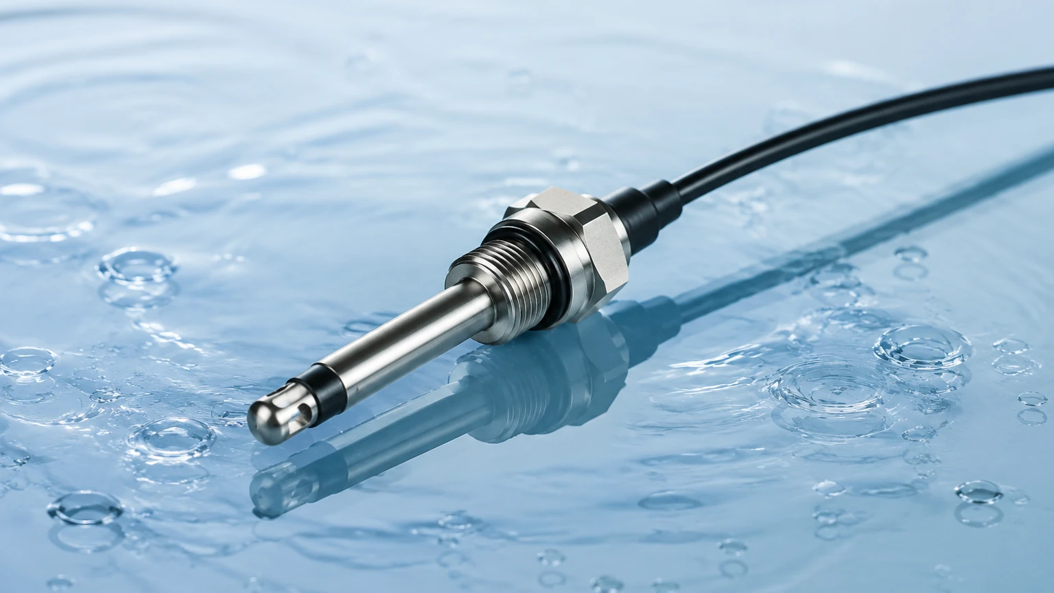
In a contacting probe, the electrodes come into direct contact with the process fluid. These are the most common sensors for low-to-medium conductivity applications.
* Two-Electrode Sensors: The simplest design, suitable for pure and ultrapure water. However, they are susceptible to "polarization," where a layer of ions builds up at the electrode surface, creating an artificial resistance.
* Four-Electrode Sensors: These use two drive electrodes to pass a current and two sensing electrodes to measure the voltage drop. This design eliminates errors caused by polarization and cable resistance, making them ideal for high-range measurements and applications where slight fouling may occur.
2. Inductive (Toroidal) Conductivity Probes
Inductive probes do not have electrodes that touch the liquid. Instead, they use two wire-wound metal toroids (coils) encased in a plastic or ceramic housing. One coil induces an electric current in the liquid, and the second coil detects the strength of that current.
* Advantages: Since there are no metal electrodes to corrode or foul, inductive probes are the preferred choice for aggressive chemicals, high-salinity brine, and liquids with high suspended solids (slurries).
* Limitations: They generally cannot measure very low conductivity (below 50 µS/cm) because the induced signal becomes too weak to detect accurately.
Selection Criteria for Industrial Conductivity Probes
Choosing the right water conductivity probe requires a thorough analysis of the process environment. The following table provides a comparison to assist in the initial selection process.
| Feature | Contacting (2-Electrode) | Contacting (4-Electrode) | Inductive (Toroidal) |
| :— | :— | :— | :— |
| Measurement Range | 0.01 µS/cm to 1,000 µS/cm | 10 µS/cm to 1,000 mS/cm | 50 µS/cm to 2,000 mS/cm |
| Best Application | Ultrapure water, Boiler feed | General process water | Acids, Brine, Wastewater |
| Fouling Resistance | Low | Moderate | High |
| Maintenance Needs | High (Cleaning required) | Moderate | Low |
| Material Options | Stainless Steel, Graphite | Stainless Steel, Titanium | PEEK, PFA, PP |
| Accuracy | Very High | High | Moderate |
Material Compatibility
For chemical applications, the probe body and electrode material must withstand the process fluid. While 316L Stainless Steel is standard for water, Titanium or Monel may be required for seawater. For inductive probes, PEEK (Polyether ether ketone) is often used for its excellent chemical resistance and high-temperature stability.
Installation and Engineering Considerations
Correct installation is vital to ensure that the water conductivity probe provides a representative reading of the process. Poor placement can lead to air entrapment or sediment buildup, both of which cause significant measurement errors.
1. Full Pipe Requirement: The sensor must always be fully submerged in the liquid. In horizontal pipes, install the probe on the side or bottom to avoid air pockets that naturally collect at the top of the pipe.
2. Flow Direction: For contacting probes, the flow should ideally be directed into the electrode opening to ensure a constant refresh of the sample and to prevent the accumulation of stagnant ions.
3. Avoidance of Obstructions: Ensure there is sufficient clearance around the sensor tip. For inductive probes, being too close to a metallic pipe wall can interfere with the magnetic field, leading to inaccurate readings. A minimum clearance of 20mm to 50mm from the pipe wall is typically recommended depending on the sensor size.
4. Grounding: In systems with significant electrical noise or plastic piping, proper grounding of the transmitter and the process liquid is necessary to prevent stray currents from interfering with the low-voltage signals of the probe.
When designing a complete liquid management system, engineers often pair conductivity monitoring with advanced level measurement to ensure both the quality and quantity of the medium are controlled. For a broader range of industrial instrumentation, including radar and ultrasonic sensors that complement water quality monitoring, visit the Main Page to explore integrated solutions.
Maintenance, Calibration, and Troubleshooting
Even the most advanced water conductivity probe requires periodic maintenance to ensure long-term accuracy.
Cleaning Procedures
Fouling is the most common cause of measurement drift. Oils, scale, and biological growth can coat the electrodes, increasing the measured resistance and resulting in a lower-than-actual conductivity reading.
* Soft Deposits: Can be removed with a soft brush and mild detergent.
* Mineral Scale: Requires a brief soak in a weak acid solution (e.g., 5% Hydrochloric acid).
* Oily Films: Should be cleaned with an appropriate solvent like isopropyl alcohol, followed by a thorough rinse with deionized water.
Calibration Best Practices
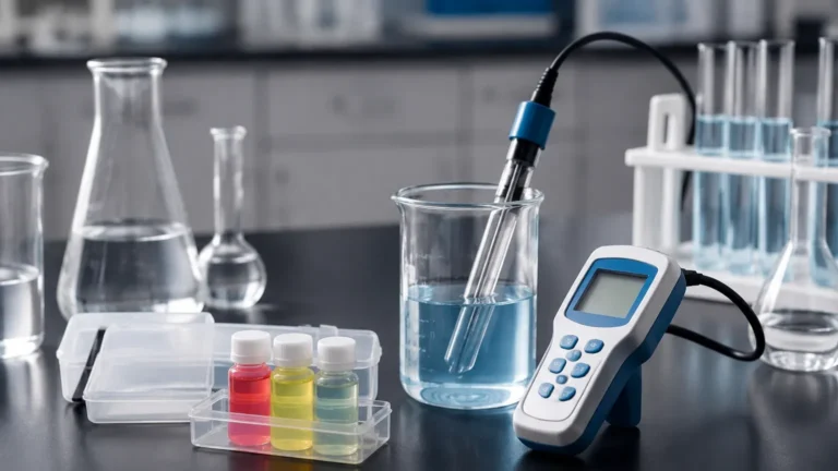
Calibration should be performed using certified standard solutions that bracket the expected process range. For example, if your process typically runs at 500 µS/cm, you should calibrate using a 1,413 µS/cm standard.
It is important to note that conductivity standards are sensitive to CO2 absorption from the air, which can change their value over time. Always use fresh standards and ensure the probe and the container are clean to avoid cross-contamination.
Limitations and Potential Risks
While highly reliable, water conductivity probes have specific limitations:
* Non-Selective Measurement: Conductivity measures the total ionic content. It cannot distinguish between different types of ions (e.g., it cannot tell the difference between Sodium Chloride and Calcium Carbonate). If specific ion concentration is required, pH or Ion-Selective Electrodes (ISE) must be used in conjunction.
* Pressure and Temperature Limits: Standard plastic-bodied probes may be limited to 6-10 bar (87-145 psi) and temperatures below 60°C. High-pressure boilers require specialized stainless steel probes with ceramic insulators designed to withstand up to 100 bar and 200°C.
* Cable Length Interference: For contacting sensors, long cable runs can introduce capacitance and resistance errors. It is often better to use a transmitter with a digital output (like Modbus or HART) located close to the sensor.
Frequently Asked Questions (FAQs)
Q: How often should I calibrate my conductivity probe?
A: In stable, clean water applications, quarterly calibration is often sufficient. In high-fouling wastewater or chemical processes, weekly or even daily verification may be required.
Q: Can I use a conductivity probe to measure the concentration of sulfuric acid?
A: Yes, inductive (toroidal) probes are frequently used for this. Because the relationship between concentration and conductivity is well-defined for many acids, the transmitter can be programmed to display "Percent Concentration" instead of mS/cm.
Q: What is the difference between Conductivity and TDS?
A: TDS (Total Dissolved Solids) is a measure of the mass of dissolved material in the water (expressed in mg/L or ppm). Conductivity is an electrical measurement. Transmitters use a conversion factor (typically between 0.5 and 0.7) to estimate TDS from conductivity.
Q: Why is my reading fluctuating wildly?
A: This is often caused by air bubbles passing through the sensor or poor grounding. Check the installation orientation and ensure the pipe is full. If the problem persists, verify the shielding and grounding of the sensor cable.
Conclusion
The water conductivity probe is a cornerstone of industrial liquid analysis. By selecting the appropriate technology—whether a precision 2-electrode sensor for ultrapure water or a rugged inductive probe for aggressive chemicals—operators can ensure their processes remain within specified parameters. Proper installation, consistent calibration, and an understanding of the underlying physics are the keys to leveraging this technology for optimized industrial automation and water management.