Pipe Surface Thermometers
Pipe Surface Thermometers
In industrial process control, monitoring the temperature of fluids within a piping system is a fundamental requirement. While invasive sensors—such as thermowells—are common, they require cutting into the pipe, which introduces potential leak points and complicates maintenance. Pipe surface thermometers offer a non-invasive alternative, measuring the temperature of the pipe wall to infer the internal fluid temperature. This guide explores the engineering principles, selection criteria, and practical applications of these instruments in B2B industrial environments.
Understanding Measurement Principles for Surface Temperature
The operation of pipe surface thermometers relies on the principle of thermal conduction. Heat energy from the process fluid transfers through the pipe wall to the external surface. The sensor, mounted on the outside of the pipe, must reach thermal equilibrium with that surface to provide an accurate reading.
Thermal Conduction and Equilibrium
In an ideal scenario, the pipe wall temperature would perfectly match the fluid temperature. However, in practice, a temperature gradient exists across the pipe wall. The sensor measures the "skin" temperature. To ensure this value closely approximates the internal fluid temperature, the sensor must be shielded from ambient environmental conditions. Without proper insulation, the sensor may be cooled by ambient air or heated by solar radiation, leading to significant measurement errors.
Sensor Technologies
Several technologies are utilized within pipe surface thermometers to convert thermal energy into a readable signal:
1. Bimetallic Elements: These consist of two bonded metal strips with different coefficients of thermal expansion. As temperature changes, the strip coils or uncoils, moving a mechanical pointer across a dial. These are typically used for local indication without the need for external power.
2. Resistance Temperature Detectors (RTDs): Usually employing Pt100 or Pt1000 platinum elements, RTDs measure temperature by monitoring the change in electrical resistance. They are highly accurate and stable over long periods.
3. Thermocouples: These utilize the Seebeck effect, where a voltage is generated at the junction of two dissimilar metals. They are preferred for high-temperature applications or where a fast response time is required.
Common Types of Pipe Surface Thermometers
Selecting the right mounting style is as critical as selecting the sensor technology. The mounting method determines how effectively the sensor maintains contact with the pipe surface.
Magnetic Surface Thermometers
These instruments utilize high-strength magnets to adhere to ferrous pipes. They are ideal for temporary spot-checking or diagnostic tasks where a permanent installation is not required. However, they are limited to carbon steel or magnetic alloy piping and are not suitable for stainless steel or plastic lines.
Clamp-on and Strap-on Sensors
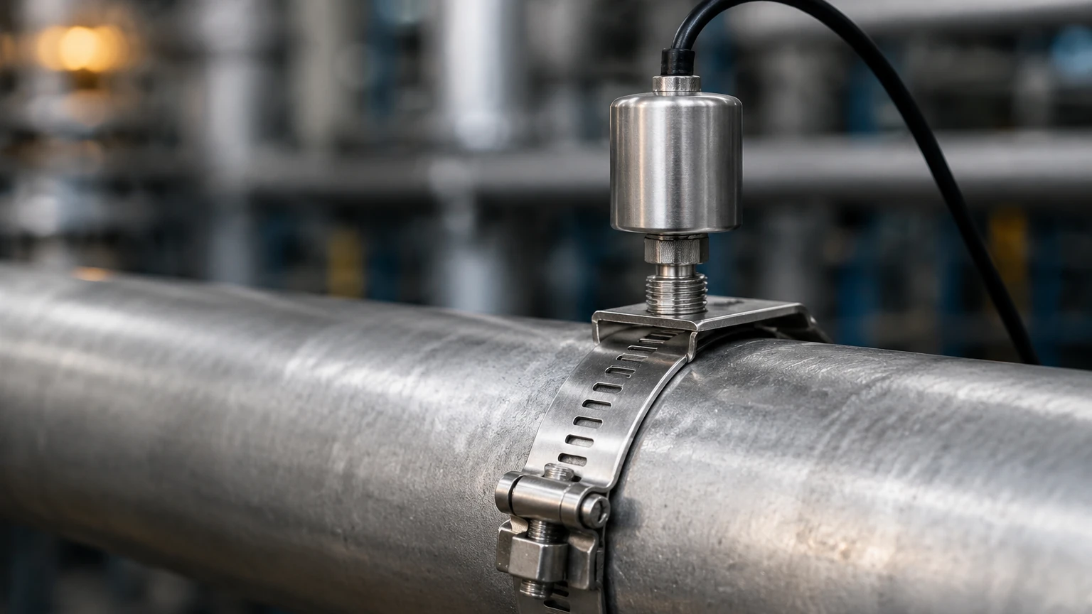
For permanent installations, clamp-on thermometers use metal bands or adjustable straps to secure the sensor housing against the pipe. This method is universal, working on any pipe material including stainless steel, copper, and PVC. These are often used in HVAC and water treatment applications where system integrity cannot be compromised by drilling.
Spring-Loaded Sensors
Often integrated into a housing that is strapped to the pipe, a spring-loaded mechanism ensures that the sensor tip maintains constant, firm pressure against the pipe surface. This compensates for vibrations and thermal expansion/contraction of the pipe, which might otherwise create a gap between the sensor and the surface.
Technical Selection Criteria and Evaluation
When specifying pipe surface thermometers for industrial projects, engineers must evaluate several parameters to ensure the device meets the application's demands. The following table provides a general comparison of common configurations:
| Feature | Bimetallic Dial | RTD (Clamp-on) | Thermocouple (Strap-on) |
| :— | :— | :— | :— |
| Typical Accuracy | ±2% to 5% of scale | ±0.3°C to ±0.5°C | ±1.1°C to ±2.2°C |
| Temperature Range | -50°C to 400°C | -200°C to 600°C | -200°C to 1200°C |
| Response Time | Slow (Mechanical) | Moderate | Fast |
| Output Signal | Visual Dial Only | 4-20mA / Modbus / RTD | Millivolt / 4-20mA |
| Power Requirement | None | Required for transmitter | None (Passive) |
Pipe Diameter and Geometry
The curvature of the pipe impacts the contact area. Sensors designed for a 50 mm (2 inch) pipe may not seat properly on a 500 mm (20 inch) main. Many B2B suppliers provide contoured sensor blocks or flexible thin-film elements to maximize the contact patch across various diameters.
Environmental Resistance
In chemical processing or offshore oil and gas environments, the thermometer housing must withstand corrosive atmospheres. Look for 316L stainless steel construction and Ingress Protection (IP) ratings of IP66 or higher. For hazardous areas, sensors must be certified as Intrinsically Safe (IS) or Explosion-Proof (Ex).
Installation Considerations and Best Practices
The accuracy of a surface measurement is highly dependent on the quality of the installation. Even the most expensive RTD will fail if it is not thermally coupled to the pipe.
1. Surface Preparation: The pipe surface must be cleaned of rust, scale, paint, and debris. A smooth, bare metal surface provides the lowest thermal resistance. In some cases, a light sanding is recommended.
2. Thermal Transfer Compound: Applying a thin layer of high-temperature thermal grease or conductive paste between the sensor and the pipe is essential. This fills microscopic air gaps, significantly improving heat transfer and reducing response lag.
3. Insulation (Lagging): This is the most overlooked step. The sensor and a portion of the pipe (at least 150 mm or 6 inches on either side) should be covered with industrial insulation. This prevents the ambient air from influencing the sensor temperature, ensuring the sensor reads the pipe wall temperature accurately.
4. Orientation: On horizontal pipes carrying liquids, it is generally best to mount the sensor at the 3 o'clock or 9 o'clock position. Mounting at the top (12 o'clock) can result in measuring trapped air/gas, while the bottom (6 o'clock) may measure accumulated sediment.
Limitations and Potential Error Sources
While pipe surface thermometers are convenient, engineers must be aware of their inherent limitations compared to invasive thermowells.
* Thermal Lag: Because the heat must travel through the pipe wall and the sensor housing, there is a delay in detecting rapid temperature fluctuations. In systems requiring high-speed PID control, invasive sensors may still be necessary.
* Pipe Material Conductivity: Plastic pipes (PVC, HDPE) have very low thermal conductivity. Surface thermometers on plastic pipes will have a much slower response and higher error margin than those on copper or steel pipes.
* Ambient Interference: If the insulation is insufficient or becomes wet, the sensor will likely read lower than the actual fluid temperature in cold environments, or higher in hot environments.
Integration with Level Measurement Systems
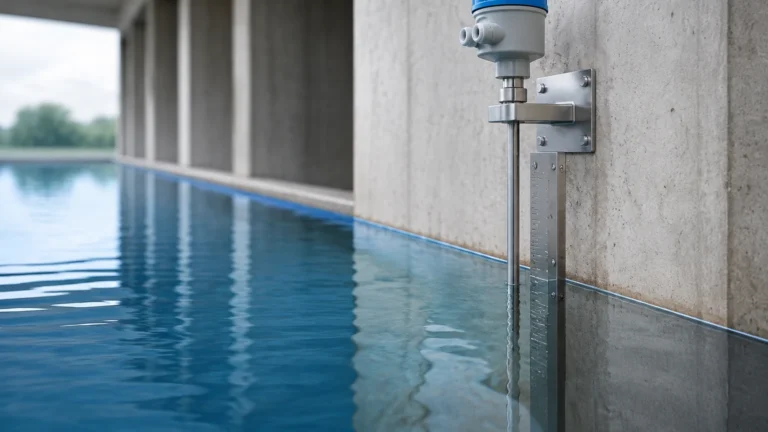
In many industrial automation setups, temperature data from pipe surfaces is used to support other process measurements. For instance, the density of a liquid changes with its temperature. When using hydrostatic level transmitters to measure the volume of a tank, the system must account for these density changes to maintain accuracy. Similarly, advanced radar level meters may use temperature data to compensate for changes in the dielectric constant of certain vapors or to monitor the structural integrity of the vessel.
For engineers looking to optimize their entire process loop, integrating reliable temperature data is a prerequisite for high-precision level control. You can Review product options and application support to see how surface temperature monitoring complements advanced level measurement technologies in water treatment, chemical, and oil and gas applications.
Frequently Asked Questions (FAQ)
Q: Can I use a pipe surface thermometer on an insulated pipe?
A: Yes, but you must remove a small section of the insulation to mount the sensor directly to the pipe wall. After installation, the sensor should be re-insulated to ensure accuracy.
Q: How much error should I expect compared to an internal probe?
A: In a well-installed, insulated system on a metal pipe, the difference is often less than 1°C to 2°C (1.8°F to 3.6°F). On uninsulated pipes, the error can exceed 10°C (18°F) depending on the ambient temperature.
Q: Are these suitable for high-pressure steam lines?
A: Yes, because they do not penetrate the pipe, they are excellent for high-pressure systems where a thermowell failure could be catastrophic. However, ensure the sensor and its mounting hardware are rated for the high external temperatures of the steam pipe.
Q: What is the maintenance requirement for surface sensors?
A: Maintenance is minimal. Periodically check that the mounting straps are tight and that the thermal paste has not dried out or migrated, especially in high-vibration environments.
By following these engineering guidelines, B2B procurement and maintenance teams can successfully implement pipe surface thermometers as a reliable, cost-effective, and safe method for process temperature monitoring. Whether used for simple local indication or as part of a complex automated control system, these instruments provide the data necessary for efficient industrial operations.