Ve1
Ve1
In the landscape of industrial automation, the precision of liquid and solid level measurement is a cornerstone of operational efficiency and safety. The ve1 series of level measurement instruments represents a critical category of sensors designed to bridge the gap between high-end specialized equipment and versatile, cost-effective industrial monitoring. Whether managing water treatment facilities, chemical processing plants, or oil and gas storage, understanding the technical nuances of the ve1 configuration is essential for process engineers and procurement specialists.
This guide provides a comprehensive technical analysis of ve1 level measurement technology, detailing its underlying principles, selection criteria, and practical application in modern industrial environments.
Understanding the Measurement Principles of the Ve1 Series
Before selecting a specific ve1 instrument, it is vital to understand the physics governing the measurement. Industrial level meters generally fall into two categories: contact and non-contact. The ve1 designation often encompasses both ultrasonic and radar-based technologies, each utilizing distinct wave propagation methods.
Ultrasonic Measurement Principle
Ultrasonic ve1 sensors operate on the "Time-of-Flight" (ToF) principle. The sensor emits a high-frequency acoustic pulse (typically between 20 kHz and 70 kHz) from the transducer face. This pulse travels through the air, reflects off the surface of the medium, and returns to the sensor.
The distance is calculated using the formula:
*Distance = (Speed of Sound × Time) / 2*
Because the speed of sound is influenced by air temperature, integrated temperature compensation is a standard feature in ve1 ultrasonic units. These are ideal for open-channel flow and atmospheric storage tanks where the medium does not produce excessive foam or vapor.
Radar (Microwave) Measurement Principle
Radar-based ve1 transmitters utilize electromagnetic waves, typically in the 26 GHz or 80 GHz range. Unlike ultrasonic waves, radar pulses are not affected by air temperature, pressure, or vacuum. There are two primary methods used:
1. Pulse Radar: Similar to ultrasonic, it measures the time it takes for a microwave pulse to return.
2. FMCW (Frequency Modulated Continuous Wave): The sensor emits a continuous signal with a varying frequency. The difference in frequency between the emitted and received signal is proportional to the distance.
Radar ve1 sensors are preferred for high-pressure environments or where the dielectric constant (εr) of the material is stable enough to reflect electromagnetic energy.
Key Technical Specifications and Evaluation Criteria
When evaluating a ve1 level meter for a specific project, several technical parameters must be scrutinized to ensure long-term reliability. For more detailed technical data sheets, users often refer to the Main Page of the manufacturer’s documentation.
1. Accuracy and Resolution
Standard ve1 instruments typically offer an accuracy of ±2 mm to ±5 mm (approximately ±0.08 to ±0.2 inches). In precision-critical applications, such as custody transfer or chemical dosing, higher-resolution radar units are required. Resolution refers to the smallest change in level that the sensor can detect, which is often as fine as 1 mm.
2. Measuring Range (Beam Angle)
The measuring range of a ve1 sensor can vary from 5 meters (16.4 ft) for small tanks to 30 meters (98.4 ft) or more for large silos. A critical factor is the beam angle. A narrower beam angle (e.g., 3° to 8°) allows the sensor to avoid internal tank obstructions like ladders, agitators, or heating coils.
3. Material Compatibility
The wetted parts of the ve1 sensor—the parts in contact with the process atmosphere—must be chemically resistant. Common materials include:
* PVDF/PTFE: For corrosive acids and bases.
* Stainless Steel (316L): For high-pressure or sanitary food-grade applications.
* PP (Polypropylene): For general water and wastewater use.
Practical Selection Table for Industrial Level Measurement
Choosing the right ve1 configuration requires balancing performance against environmental constraints. The following table outlines the typical application suitability for different sensor types within the ve1 category.
| Feature | Ultrasonic Ve1 | Radar (26GHz) Ve1 | Hydrostatic Ve1 |
| :— | :— | :— | :— |
| Measurement Type | Non-contact | Non-contact | Contact (Pressure) |
| Max Range | Up to 15m (49 ft) | Up to 30m+ (98 ft) | Up to 200m (656 ft) |
| Accuracy | ±0.25% of range | ±2mm to ±5mm | ±0.1% to ±0.5% span |
| Process Temp | -40°C to 80°C | -40°C to 200°C+ | -20°C to 80°C |
| Pressure Limit | Atmospheric | Up to 40 bar (580 psi) | Depth dependent |
| Best Use Case | Water/Wastewater | Chemicals, Oil, Solids | Deep wells, vented tanks |
| Foam Resistance | Poor | Moderate to Good | Excellent (unaffected) |
Installation Considerations and Best Practices
Even the most advanced ve1 sensor will fail to provide accurate data if installed incorrectly. Engineering teams should adhere to the following installation guidelines:
Sensor Positioning
* The 1/6 Rule: For cylindrical tanks, the sensor should ideally be placed at 1/6 of the tank diameter from the side wall. This minimizes interference from wall reflections while staying clear of the center, where multiple reflections (echoes) can converge.
* Avoid the Inflow: Never install a ve1 sensor directly above the filling stream. The turbulence and falling material will cause signal scattering and false readings.
* Dead Band (Blocking Distance): Every non-contact sensor has a "dead band" near the transducer face (typically 0.2m to 0.5m). Ensure the maximum liquid level never enters this zone, as the sensor will be unable to process the return signal.
Mounting and Alignment
For solid materials (silos), the ve1 sensor should be mounted with an adjustable flange to align the beam with the angle of repose of the material. For liquids, the sensor face must be perfectly parallel to the liquid surface. In outdoor installations, a sunshade is recommended to prevent temperature spikes from affecting the internal electronics and the speed-of-sound calculations in ultrasonic models.

Limitations and Application Risks
While the ve1 series is highly versatile, certain environmental factors can compromise measurement integrity. Awareness of these risks allows for the implementation of corrective measures.
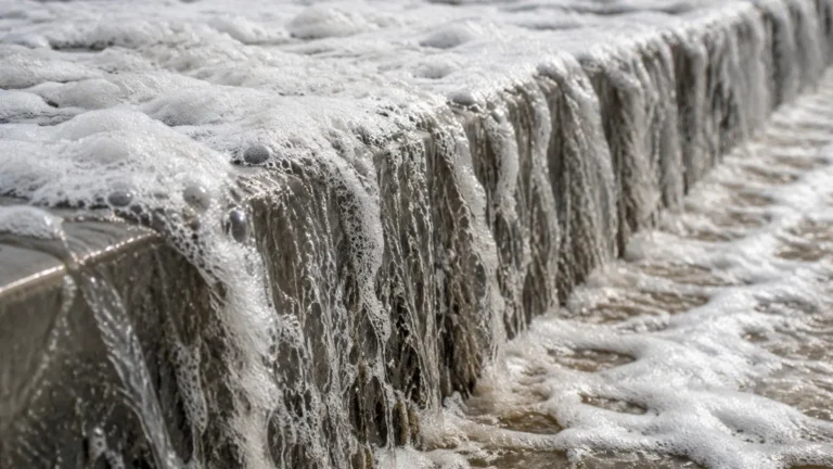
1. Heavy Foam: In wastewater treatment or chemical mixing, thick foam can absorb ultrasonic and radar signals. If foam is a constant presence, a hydrostatic transmitter or a guided wave radar (GWR) may be a more robust alternative.
2. Vacuum Conditions: Ultrasonic ve1 sensors cannot operate in a vacuum because sound waves require a medium (air/gas) to travel. Radar is the only non-contact option for vacuum-rated vessels.
3. Dust and Vapor: High concentrations of dust (in grain silos) or heavy steam (in boiler tanks) can attenuate signals. Choosing a high-frequency radar (80 GHz) often mitigates these issues due to its better signal penetration and focus.
4. Internal Obstructions: If a tank has complex internal geometry, such as baffles or cooling jackets, the sensor may pick up "false echoes." Most modern ve1 units include software for "False Echo Suppression," allowing the user to map out and ignore stationary reflections.
Frequently Asked Questions Regarding Ve1 Deployment
Q: Can a ve1 ultrasonic sensor be used for fuel level measurement?
A: It is generally not recommended for volatile fuels like gasoline because the vapor concentration changes the speed of sound, leading to significant errors. A radar-based ve1 or a magnetic level gauge is a safer and more accurate choice.
Q: How often does a ve1 transmitter require calibration?
A: In stable environments (e.g., water storage), an annual check is sufficient. In corrosive or high-temperature applications, semi-annual calibration is advised to account for any sensor face degradation or electronic drift.
Q: What is the difference between 2-wire and 4-wire ve1 models?
A: 2-wire models are loop-powered, meaning the 4-20mA signal and power share the same pair of wires. This is ideal for standard PLC integration. 4-wire models have separate power and signal lines, typically used when the sensor requires more power for heated displays or high-power transducers.
Conclusion
The ve1 category of level meters provides a reliable foundation for industrial process control. By understanding the distinctions between ultrasonic and radar technologies, respecting installation boundaries like the dead band and beam angle, and selecting materials compatible with the process media, engineers can ensure high uptime and accurate data.
For professionals seeking to compare specific models or request customized OEM/ODM services for their unique applications, visiting the manufacturer's Main Page is the recommended next step. Accessing detailed technical support and product catalogs ensures that the chosen ve1 solution aligns perfectly with the operational demands of the facility.