Rosemount Radar Level Transmitter Manual
Rosemount Radar Level Transmitter Manual: An Engineering Guide to Implementation
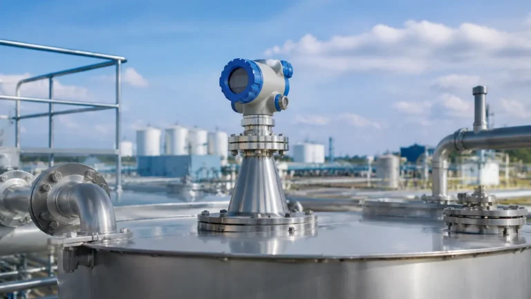
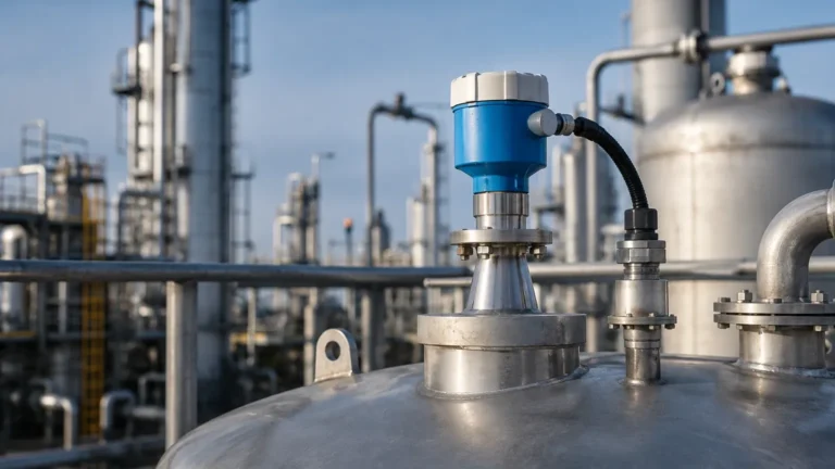
In the landscape of industrial automation, precise level measurement is critical for safety, inventory management, and process efficiency. Among the various technologies available, non-contacting radar has emerged as a gold standard for challenging environments. For many instrumentation engineers, the rosemount radar level transmitter manual serves as the definitive technical reference for deploying these devices.
Understanding the engineering principles behind Radar Level Meters is essential before proceeding with installation or configuration. This guide provides a technical overview of radar measurement principles, selection criteria based on manual specifications, and practical installation considerations for industrial applications.
Measurement Principles of Radar Level Technology
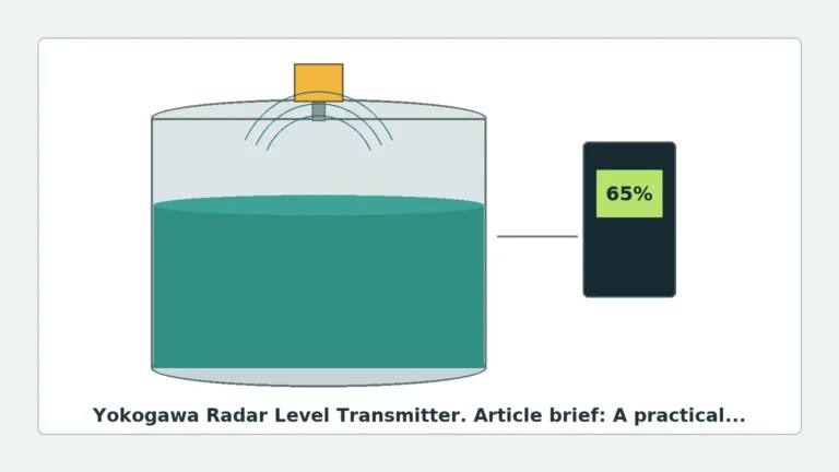
Radar level transmitters operate by emitting electromagnetic waves—typically in the microwave spectrum—and measuring the time it takes for these waves to reflect off the process medium and return to the sensor. There are two primary methods used in modern industrial radar systems: Pulse Radar and Frequency Modulated Continuous Wave (FMCW).
1. Pulse Radar (Time-of-Flight)
Pulse radar transmitters emit a short microwave pulse toward the product surface. The device measures the "Time-of-Flight" (ToF) from emission to reception. Since the speed of light is constant, the distance is calculated as:
*Distance = (Speed of Light × Time-of-Flight) / 2*
This technology is known for its energy efficiency and is often used in loop-powered (2-wire) applications.
2. Frequency Modulated Continuous Wave (FMCW)
FMCW radar emits a continuous signal with a constantly changing frequency. The reflection from the product surface is received and compared to the signal being emitted at that moment. The frequency difference between the transmitted and received signal is directly proportional to the distance. FMCW is generally preferred for high-precision requirements and applications with significant turbulence or foam.
The Role of the Dielectric Constant ($ε_r$)
The reliability of a radar signal depends heavily on the dielectric constant of the material being measured. Materials with high dielectric constants (e.g., water, $ε_r ≈ 80$) reflect radar waves strongly. Materials with low dielectric constants (e.g., hydrocarbons, $ε_r < 2.0$) allow more waves to penetrate, resulting in a weaker return signal. When consulting a Rosemount radar level transmitter manual, engineers must verify the minimum dielectric threshold for the specific antenna model selected.
Technical Selection Criteria
Choosing the correct radar transmitter requires matching the instrument's frequency and antenna design to the specific process conditions.
Frequency Considerations
* Low Frequency (approx. 6 GHz): Best for applications with heavy steam, dust, or foam. The longer wavelength can penetrate vapor more effectively but requires larger antennas to maintain a narrow beam.
* High Frequency (26 GHz to 80 GHz): Higher frequencies allow for smaller antennas and provide a narrower beam angle. This is ideal for tall, narrow tanks or vessels with internal obstructions like agitators or heating coils.
Antenna Types
| Antenna Type | Typical Application | Advantages |
| :— | :— | :— |
| Horn Antenna | Large tanks, storage vessels | Robust, handles high temperatures and pressures. |
| Process Seal/Parabolic | Corrosive chemicals | Isolate the electronics from the process; easy to clean. |
| Rod Antenna | Small nozzles, hygienic applications | Fits into narrow openings; often used in pharmaceutical or food industries. |
| Guided Wave (GWR) | Low dielectric fluids, interface measurement | Directs the signal along a probe, minimizing signal loss. |
Installation Guidelines and Constraints
Correct physical installation is the most critical factor in ensuring the accuracy of Radar Level Meters. Most technical manuals emphasize the following mechanical constraints:
1. Nozzle Positioning
The transmitter should not be mounted in the center of a tank (to avoid multiple reflections from the tank walls) nor too close to the wall (to avoid signal interference). A common rule of thumb is to install the device at 1/4 to 1/6 of the tank diameter from the wall.
2. Avoiding Obstructions
The radar beam spreads as it travels. Any internal structure—such as ladders, pipes, or agitators—within the "beam cone" will create false echoes. If an obstruction is unavoidable, many modern transmitters offer "False Echo Suppression" or "Echo Mapping" via their software interface to ignore these static reflections.
3. Nozzle Geometry
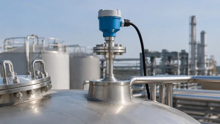
The nozzle height should be kept as short as possible. If the nozzle is too long, the radar signal may reflect off the bottom edge of the nozzle before entering the tank, creating a "dead zone" at the top of the vessel. The Rosemount radar level transmitter manual typically specifies a maximum nozzle length-to-diameter ratio for each antenna type.
Configuration and Electrical Setup
Once mechanically installed, the device must be configured to the specific vessel dimensions. This is usually performed via a HART communicator, a local display interface, or specialized PC software (such as Rosemount Radar Master).
Key Configuration Parameters:
* Reference Point: Usually the flange face or the bottom of the sensor.
* Tank Height: The distance from the reference point to the zero level (usually the tank bottom).
* Upper Range Value (20mA): The level corresponding to the maximum desired measurement.
* Lower Range Value (4mA): The level corresponding to the minimum desired measurement.
* Damping: A time constant (in seconds) used to smooth out fluctuations caused by surface turbulence.
Limitations and Application Risks
While radar is highly versatile, it is not a universal solution. Engineers must be aware of the following limitations:
* Heavy Foam: Extremely dense, thick foam can absorb the radar signal entirely, leading to a "Loss of Echo" (LOE) condition. In these cases, guided wave radar or ultrasonic sensors might be considered, though radar remains superior for light foam.
* Vacuum Conditions: While radar works in a vacuum (unlike ultrasonic sensors), high-vacuum seals are required to prevent leakage through the process connection.
* Solid Materials: Measuring the level of solids (grains, powders, ores) requires high-frequency radar and often a swiveling mounting flange to account for the "angle of repose" of the material surface.
Maintenance and Troubleshooting
Radar transmitters are generally low-maintenance because they have no moving parts. However, build-up on the antenna can degrade performance over time.
Common Troubleshooting Steps found in a Rosemount radar level transmitter manual:
1. Check Signal Strength: If the signal-to-noise ratio is low, inspect the antenna for coating or condensation.
2. Verify Dielectric Settings: If the level reading is inconsistent, ensure the configured dielectric constant matches the actual process fluid.
3. Update Echo Map: If the transmitter is locking onto an internal tank structure, re-run the false echo suppression routine while the tank is as empty as possible.
Frequently Asked Questions (FAQ)
Q: Can radar measure the interface between two liquids?
A: Standard non-contact radar is generally used for total level. For liquid-liquid interface (e.g., oil over water), Guided Wave Radar (GWR) is the preferred technology as it can detect the change in dielectric constant at the interface layer.
Q: What is the typical accuracy of an industrial radar level meter?
A: Most high-end industrial radars offer accuracy ranging from ±1 mm to ±3 mm, depending on the frequency and process conditions.
Q: Does temperature or pressure affect radar accuracy?
A: Unlike ultrasonic waves, radar waves are electromagnetic and do not require a medium for travel. Therefore, changes in air temperature, pressure, or vapor composition have a negligible effect on the speed of the signal and the resulting accuracy.
Q: How do I handle condensation on the antenna?
A: Many manuals recommend using antennas with a PTFE or PFA drip shield. For extreme condensation, some models allow for a specialized air purge connection to keep the antenna face clear.
Summary Table for Engineering Selection
| Feature | Pulse Radar | FMCW Radar |
| :— | :— | :— |
| Best For | General purpose, battery/loop power | High precision, turbulent surfaces |
| Power Consumption | Low | Moderate to High |
| Accuracy | Standard (±3-5mm) | High (±1mm) |
| Complexity | Moderate | High |
| Cost | Generally lower | Generally higher |
By following the technical specifications outlined in the rosemount radar level transmitter manual and adhering to rigorous installation standards, engineers can ensure long-term reliability and precision in their level measurement systems. For further technical specifications on various models, professionals should always refer to the specific data sheets provided by the manufacturer to confirm compatibility with their process environment.