Rheonik Coriolis Mass Flow Transmitters
Rheonik Coriolis Mass Flow Transmitters
In the landscape of industrial process control, the precision of fluid measurement is a cornerstone of operational efficiency, safety, and fiscal accountability. Among the various technologies available for measuring fluid dynamics, Coriolis mass flow meters are often regarded as the gold standard due to their ability to measure mass flow directly, independent of the fluid's physical properties. Rheonik Coriolis mass flow transmitters, specifically known for their unique Omega-shaped tube design, represent a specialized segment of this technology, engineered to handle extreme pressures and temperatures that often challenge standard instrumentation.
For engineers and procurement professionals in the chemical, oil and gas, and power generation sectors, understanding the nuances of these transmitters is essential for selecting the right equipment. This guide explores the measurement principles, selection criteria, and installation requirements for Rheonik Coriolis systems, while also considering how these measurements integrate into broader process automation frameworks.
The Fundamental Principle of Coriolis Mass Flow Measurement
Before evaluating specific transmitter models, it is vital to understand the physics that allows a Coriolis meter to function. Unlike volumetric flow meters (such as turbine or ultrasonic meters), which measure the space a fluid occupies, a Coriolis meter measures the actual mass of the fluid passing through the device.
The Coriolis Effect
The measurement is based on the Coriolis effect, a phenomenon where an inertial force acts on an object moving within a rotating frame of reference. In a flow meter, this is achieved by vibrating the internal flow tubes at their resonant frequency using an electromagnetic drive coil.
When a fluid (liquid or gas) flows through these vibrating tubes, it experiences a Coriolis acceleration. This acceleration induces a slight twisting or phase shift in the tube's vibration. Sensors located at the inlet and outlet sides of the tube pick up these vibrations. When there is no flow, the tubes vibrate in unison (in phase). As flow increases, the Coriolis force causes the inlet and outlet sections to vibrate out of sync. This phase shift is directly proportional to the mass flow rate.
Direct Density and Temperature Measurement
In addition to mass flow, Coriolis transmitters simultaneously measure the resonant frequency of the tubes. Since the resonant frequency changes based on the mass of the tubes and the fluid inside them, the transmitter can calculate the fluid's density in real-time. Furthermore, an integrated Pt100 or Pt1000 temperature sensor monitors the tube temperature to compensate for changes in material elasticity, providing a third process variable: temperature.
Design Characteristics of Rheonik Omega Tube Sensors
Rheonik is distinguished in the marketplace by its "Omega" tube geometry. While many manufacturers use U-shaped or straight tubes, the Omega design offers specific mechanical advantages for high-performance B2B applications.
1. High Pressure Resistance: The curved shape of the Omega tube allows for thicker wall constructions without sacrificing the sensitivity required to detect the Coriolis force. This makes these transmitters suitable for applications exceeding 1,000 bar (100 MPa).
2. Torsional Stress Distribution: The design naturally distributes mechanical stress more evenly across the tube structure. This longevity is critical in high-cycle industrial environments where fatigue can lead to tube failure in lesser designs.
3. Low Pressure Drop: Despite the curvature, the internal diameter and path are optimized to minimize the energy loss (pressure drop) of the fluid as it passes through the meter, which is a key consideration for pump sizing and energy efficiency.
Selection Criteria and Technical Specifications
Selecting a Rheonik Coriolis mass flow transmitter requires a detailed analysis of the process conditions. Because these instruments are a significant capital investment, matching the sensor (RHM series) and the transmitter electronics (RHE series) to the application is paramount.
Material Compatibility
Standard sensors are typically constructed from 316L stainless steel (1.4404). However, for corrosive media like wet chlorine or high-concentration acids, exotic materials such as Alloy C22 (2.4602), Tantalum, or Duplex steel are required. Engineers must verify the chemical compatibility of the wetted parts with the process fluid at the maximum operating temperature.
Flow Range and Accuracy
The following table provides a generalized overview of typical performance characteristics for different sensor sizes:
| Sensor Category | Typical Pipe Size (mm) | Max Flow Rate (kg/min) | Typical Accuracy (Liquid) | Max Pressure (Standard) |
| :— | :— | :— | :— | :— |
| Small Flow (RHM01-04) | 1 mm to 6 mm | 0.1 to 10 | ±0.10% to ±0.20% | Up to 1,000+ bar |
| Medium Flow (RHM06-20) | 10 mm to 50 mm | 50 to 500 | ±0.05% to ±0.10% | 300 – 450 bar |
| Large Flow (RHM30-160) | 80 mm to 300 mm | 1,500 to 30,000 | ±0.10% | 100 – 200 bar |
Electronics and Communication
The transmitter (the electronics unit) must support the facility's control architecture. Modern RHE series transmitters offer:
* Outputs: 4-20mA (HART), Pulse/Frequency, and Status.
* Digital Protocols: Modbus RTU/TCP, Profibus DP, Profinet, and EtherNet/IP.
* Housing: Remote-mounted for high-temperature applications or integral-mounted for compact installations.
Installation Guidelines for Optimal Performance
Even the most accurate Coriolis transmitter will perform poorly if installed incorrectly. Because the measurement relies on detecting minute vibrations, external mechanical noise and fluid conditions must be managed.
Orientation and Mounting
* Liquids: The sensor should ideally be installed in a "tubes down" orientation in horizontal pipes to ensure the tubes remain full and to allow any entrained gas to pass through. If installed in a vertical pipe, the flow must be upward to prevent air pockets.
* Gases: For gas measurement, the "tubes up" orientation is preferred to allow any condensed liquids to drain out of the sensor.
* Mechanical Support: The piping on both sides of the meter must be rigidly supported. The meter should not be the primary support for the pipe string. Use heavy-duty clamps or pedestals to isolate the meter from plant vibrations.
Avoiding Interference
* Pump Pulsation: Positive displacement pumps can create pressure waves that interfere with the meter's resonant frequency. Installing a pulsation dampener or moving the meter further downstream can mitigate this.
* Valve Cavitation: Control valves should always be placed downstream of the Coriolis meter. If a valve is placed upstream, the resulting turbulence and potential cavitation can cause significant measurement errors.
* Zero Calibration: After installation and under full process pressure and temperature, a "zero-point calibration" must be performed with the flow completely stopped (using isolation valves) to account for the specific stresses of the installed piping.

Integrating Flow and Level Measurement in Process Automation
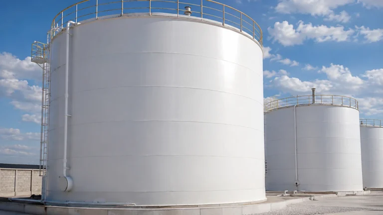
In many industrial applications, mass flow data is not used in isolation. For instance, in chemical batching or fuel storage, mass flow transmitters work in tandem with level measurement instruments to provide a complete picture of inventory and process stability.
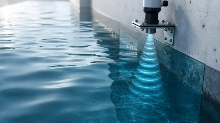
While Coriolis transmitters provide high-speed data on the fluid entering or leaving a vessel, level sensors provide the absolute reference for the volume currently held. In applications involving pressurized tanks or fluids with changing densities, relying solely on flow integration can lead to "drift" over time. By cross-referencing the totalized mass from a Rheonik transmitter with the precise level data from a radar or hydrostatic sensor, operators can perform real-time mass balance calculations to detect leaks or sensor inaccuracies.
For engineers designing these integrated systems, selecting compatible instrumentation is key. You can Review product options and application support on the Main Page of professional measurement sites to see how different level technologies—such as radar, ultrasonic, and magnetic gauges—can be paired with flow transmitters to create a robust automation loop.
Technical Limitations and Operational Considerations
Despite their versatility, Rheonik Coriolis mass flow transmitters have limitations that must be addressed during the design phase.
1. Gas Entrainment: Coriolis meters struggle with "two-phase flow" (liquid with large amounts of entrained gas). While Rheonik’s advanced electronics can compensate for some entrainment, excessive gas can dampen the tube vibration, leading to a "stalling" of the measurement or significant accuracy degradation.
2. Pressure Drop: In high-viscosity applications, the curved path of the Omega tube can result in a higher pressure drop compared to a straight-tube Coriolis meter or an ultrasonic meter. This must be calculated using the manufacturer’s sizing software.
3. Initial Cost: The complexity of the sensor and the precision of the electronics make Coriolis meters more expensive than electromagnetic or vortex meters. The investment is typically justified by the reduction in maintenance (no moving parts) and the high accuracy of the mass data.
Frequently Asked Questions (FAQs)
Q: Can Rheonik transmitters measure cryogenic fluids?
A: Yes. The Omega tube design is particularly well-suited for cryogenic applications, such as Liquid Natural Gas (LNG) or liquid hydrogen, because the material can handle the extreme thermal contraction without mechanical failure. Special cryogenic insulation and remote electronics are required.
Q: How often does a Coriolis meter need recalibration?
A: Because there are no moving parts to wear out, the physical calibration of the tubes is extremely stable. In most stable processes, a check of the zero-point and electronics every 2 to 5 years is sufficient, though regulated industries (like oil and gas custody transfer) may require annual verification.
Q: Is a straight run of pipe required before the meter?
A: Unlike turbine or orifice plate meters, Coriolis meters are generally not sensitive to flow profile disturbances. Therefore, they do not strictly require long straight runs of pipe. However, keeping them away from extreme turbulence (like immediately after a pump discharge) is still best practice for reducing noise.
Q: How does the transmitter handle varying fluid densities?
A: The transmitter calculates density automatically based on the vibration frequency. If the fluid changes from water to oil, the meter will continue to provide accurate mass flow and will also output the new density value, which can be used to identify the product or monitor mixing ratios.
By following these technical guidelines and ensuring proper installation, Rheonik Coriolis mass flow transmitters provide a reliable, high-precision solution for the most demanding industrial environments. When integrated with high-quality level measurement systems, they form the backbone of modern, data-driven process control.